Circuit board printing fixing device
A technology for fixing devices and circuit boards, applied in printing, printing machines, rotary printing machines, etc., can solve problems affecting printing accuracy, low work efficiency, circuit board offset, etc., to achieve high work efficiency, avoid slipping, and avoid movement Effect
- Summary
- Abstract
- Description
- Claims
- Application Information
AI Technical Summary
Problems solved by technology
Method used
Image

Examples
Embodiment 1
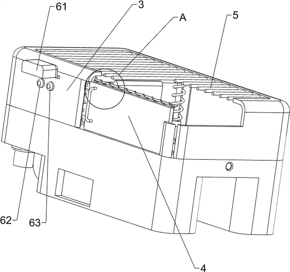
[0038] A circuit board printing fixture, such as Figure 1-Figure 6 As shown, it includes a supporting bottom box 1, a fixed base 2, a sealing top plate 3, an opening and closing plate 4, an orientation rod 41, a heat dissipation top window 5, an airtight cover 61, a start button 62, a stop button 63, a positioning mechanism 7 and a pressing function 8 The bottom of the supporting bottom box 1 is fixedly connected with a fixed base 2, the top of the supporting bottom box 1 is fixedly connected with a sealing top plate 3, and the right side of the front part of the sealing top plate 3 is fixedly fixed with a directional rod 41 symmetrically up and down, and the directional rods 41 on the upper and lower sides slide between them. The type is provided with opening and closing plate 4, and the upper part of the sealing top plate 3 is fixedly connected with the heat dissipation roof window 5, and the upper left side of the outer front side of the sealing top plate 3 is hingedly prov...
Embodiment 2
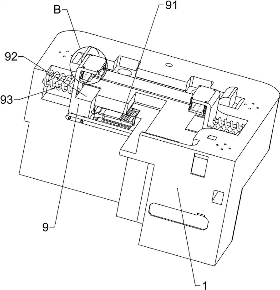
[0043] On the basis of Example 1, such as Figure 7-Figure 13 As shown, a clamping mechanism 9 is also included, and the clamping mechanism 9 includes a telescopic solenoid valve 91, a clamping bottom block 92, a positioning rod 93, a roller plate 94, a first driving rack 95, a reversing gear 96, a first The driven rack 97 and the first pressure sensor 98 are provided with a telescopic solenoid valve 91 on the upper front side of the left part of the support bottom box 1, and the positioning rods 93 are arranged at intervals on the upper left part of the support bottom box 1, and the positioning rods on the left and right sides The sliding type between 93 is provided with a clamping bottom block 92, the front clamping bottom block 92 is fixedly connected with the telescopic solenoid valve 91, the upper sliding type of the clamping bottom block 92 is provided with a roller plate 94, and the front clamping bottom block 92 is on the right side The lower part is fixedly connected ...
Embodiment 3
[0048] On the basis of embodiment 1 and embodiment 2, such as Figure 14-Figure 16 As shown, it also includes an adsorption mechanism 11, the adsorption mechanism 11 includes a rubber suction nozzle 111, a telescopic air guide tube 112, an air pump 113, a photoelectric sensor 114, a second pressure sensor 115 and a dust cover 116, and the middle part of the positioning lifting plate 1011 is provided There is a rubber suction nozzle 111, and an air suction pump 113 is provided on the middle side of the right part of the support bottom box 1. A telescopic air guide tube 112 is provided between the air suction pump 113 and the rubber suction nozzle 111 and is connected. The sensor 114 is provided with a second pressure sensor 115 on the upper front side of the inner right part of the support bottom box 1, and a dustproof cover 116 is provided at the right part of the air pump 113.
[0049] Also comprise buffering mechanism 12, buffering mechanism 12 comprises elevating ball bar 1...
PUM
 Abstract
Description
Claims
Application Information
 - R&D Engineer
- R&D Manager
- IP Professional
- Industry Leading Data Capabilities
- Powerful AI technology
- Patent DNA Extraction
Browse by: Latest US Patents, China's latest patents, Technical Efficacy Thesaurus, Application Domain, Technology Topic.
© 2024 PatSnap. All rights reserved.Legal|Privacy policy|Modern Slavery Act Transparency Statement|Sitemap