A servo valve for flow control

A technology of flow control and servo valve, which is applied in the direction of servo motor components, fluid pressure actuation devices, fluid pressure actuation system components, etc. It can solve the problems of reduced service life, easy deformation and pollution of baffles, and achieve long-term guarantee Use, reset effect is good, the effect of high structural strength

Active Publication Date: 2021-12-17
XUZHOU WUYANG TECH
View PDF0 Cites 0 Cited by
  • Summary
  • Abstract
  • Description
  • Claims
  • Application Information

AI Technical Summary

Problems solved by technology

[0003] 1. The existing servo valve deflects when the armature is energized and then drives the baffle plate connected to the bottom to rotate. After the baffle plate rotates, it approaches the nozzle on one side to reduce the oil drainage area to control the hydraulic pressure, and then through the internal The sliding control of the spool valve is carried out through the change of the hydraulic pressure, and finally the flow control is realized. This way of using the tilting of the baffle will be subjected to a large lateral hydraulic pressure and thus easily deformed, resulting in a decrease in the service life of the baffle, and in the baffle The feedback spring rod connected to the bottom of the plate is also socketed in the slide valve with a movable head. This structure not only has low strength, but also the feedback spring rod is particularly thin, which leads to poor elastic reset effect and is not conducive to long-term use;
[0004] 2. The interior of the servo valve is connected to the oil inlet and the oil return through the nozzle, and the aperture of the nozzle is set small, so that when the valve position command is not issued, if the nozzle is blocked, the hydraulic pressure inside the nozzle will also change, so that through the hydraulic pressure The cavity feeds back to the spool valve to cause false signals. At this time, the flow control is not actively carried out but caused by blockage, which is not conducive to the precise control of the servo valve. At the same time, for the impurities in the used hydraulic oil, its flow It will cause certain pollution to the inside of the valve body, which will affect the long-term use of the valve body

Method used


Image

  • A servo valve for flow control
  • A servo valve for flow control
  • A servo valve for flow control

Examples


Embodiment Construction

[0021] The following will clearly and completely describe the technical solutions in the embodiments of the present invention with reference to the accompanying drawings in the embodiments of the present invention. Obviously, the described embodiments are only some, not all, embodiments of the present invention. Based on the embodiments of the present invention, all other embodiments obtained by persons of ordinary skill in the art without making creative efforts belong to the protection scope of the present invention.

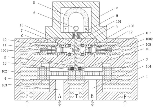
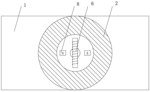
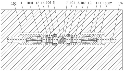
[0022] Please refer to the attached Figure 1-Figure 3 , Figure 5 , a servo valve for flow control, comprising a lower housing 1, an upper housing 2 is fixedly installed on the top of the lower housing 1, and the connection between the lower housing 1 and the upper housing 2 is located at the top of the ring groove 105, so that When the upper casing 2 is disassembled, it is convenient to replace and clean the filter cartridge 10. The middle part of the lower...


PUM


Abstract

The invention relates to the technical field of electro-hydraulic servo valves, and discloses a servo valve for flow control. An annular groove communicating with an oil pressure chamber is opened inside the top of the lower housing, and the lower housing is fixedly installed inside the annular groove. Filter cartridge, one end of the filter cartridge is fixed with an annular filter element, the lower housing is located between the inner ring of the annular filter element and the oil return hole, and a nozzle is provided, and the top of the middle section of the slide valve is movably connected with a rotating rod, and the top of the rotating rod extends into the There is an armature fixedly installed on the top of the upper shell, the outer ring of the rotating rod is located at the same height as the nozzle, and a cam is fixedly sleeved inside the upper shell. The adjusting ring extending into the inner ring of the annular filter element realizes the control of the oil drain area of ​​the nozzle through the effect of electromagnetic rotation and the cam structure, and uses the filter cartridge and the adjusting ring structure to control the hydraulic pressure, which effectively improves the accuracy and service life of the valve body .

Description

technical field [0001] The invention relates to the technical field of electro-hydraulic servo valves, in particular to a servo valve for flow control. Background technique [0002] Nowadays, it is necessary to ensure accurate and fast flow control. Manual control of the valve body is no longer used. Electric signals are used to control the valve body for flow regulation. It is not only convenient and fast, but also has high precision. The servo valve is a The commonly used flow control valve mainly refers to the electro-hydraulic servo valve. After receiving the electrical analog signal, it outputs the modulated flow and pressure accordingly. Although the servo valve is widely used, it still has certain shortcomings: [0003] 1. The existing servo valve deflects when the armature is energized to drive the baffle plate connected to the bottom to rotate. After the baffle plate rotates, it approaches the nozzle on one side to reduce the oil drainage area to control the hydraul...

Claims


Application Information

Patent Timeline
Patent Type & Authority Patents(China)
IPC IPC(8): F15B13/02F15B21/041F15B21/08
CPCF15B13/02F15B21/041F15B21/08
Inventor 周生刚卫振勇
Owner XUZHOU WUYANG TECH
Why Eureka
Try Eureka