
Power supply management circuit based on PWM (Pulse-Width Modulation) input signal

A power management and input signal technology, which is applied in battery circuit devices, circuits, circuit devices, etc., can solve the problems of reducing the service life of car batteries, poor accuracy, and untimely control

Active Publication Date: 2020-01-03
江苏春博电子科技有限公司 +1
View PDF6 Cites 0 Cited by
  • Summary
  • Abstract
  • Description
  • Claims
  • Application Information

AI Technical Summary

Problems solved by technology

[0002] Generally, the control of the car controller of the car is realized by controlling the motor through the voltage input signal, which has a relatively large energy loss in the transmission process, which is not a small waste for the car battery, which will reduce the power consumption of the car. The service life of the battery, and, through this method of control, there is still a phenomenon that the control is not timely, and the accuracy is relatively poor. At present, it is more popular to manage and control the vehicle circuit by inputting control signals. Among many control methods , various manufacturers are also in-depth research and development of a more energy-saving and low-consumption control circuit

Method used


Image

  • Power supply management circuit based on PWM (Pulse-Width Modulation) input signal

Examples


Embodiment Construction

[0016] In order to deepen the understanding of the present invention, the present invention will be further described in detail below in conjunction with the accompanying drawings and embodiments, which are only used to explain the present invention and do not limit the scope of protection.

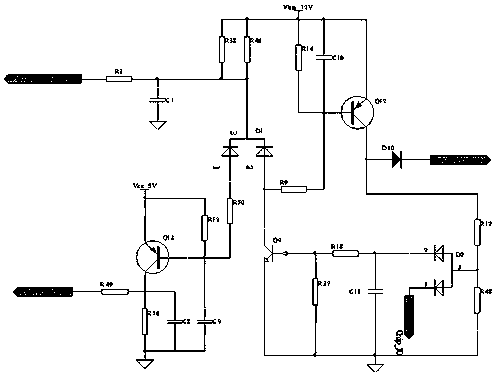
[0017] A power management circuit based on PWM input signal, such as figure 1 As shown, it includes a pulse width signal acquisition unit and a power management control unit; the pulse width signal acquisition unit includes a resistor R3, a resistor R50, a resistor R12, a resistor R49, a resistor R10, a resistor R38, a resistor R46, a capacitor C1, a capacitor C8, Capacitor C9, diode D1, transistor Q13; one end of resistor R3 is connected to the external input signal (PWM inputextern), and the other end of resistor R3 is respectively connected to one end of capacitor C1, one end of resistor R38, one end of resistor R46, and the negative polarity of diode D1 terminal (3 feet of D1), the ot...


PUM


Abstract

The invention discloses a power supply management circuit based on a PWM (Pulse-Width Modulation) input signal. The circuit comprises a pulse width signal collection unit and a power supply managementcontrol unit, wherein the pulse width signal collection unit comprises an R3, an R50, an R12, an R49, an R10, an R38, an R46, a C1, a C8, a C9, a D1 and a Q13; one end of the R3 is connected to an external input signal, and the other end of the R3 is independently connected with one end of the C1, one end of the R38, one end of the R46 and the negative polarity end of the D1; the other end of theC1 is subjected to ground connection; the other end of the R38 is connected with a power supply; the other end of the R46 is connected with the power supply; one positive polarity end of the D1 is connected to one end of the R50, and the other end of the R50 is independently connected to one end of the R12, one end of the C9 and a base electrode of the Q13; the other end of the R12 is independently connected with 5V(Vcc_5V) and an emitting electrode of the Q13; the other end of the C9 is independently connected with one end of the C8 and one end of the R10 and is connected with a ground connection end; the other end of the C8 is independently connected with a collecting electrode of the Q13, the other end of the R10 and one end of the R49; and the other end of the R49 is connected with single chip microcomputer input capture. The whole circuit is controlled by PWM signal input, is high in sensitivity, is quick in reaction, can realize the control and the maintaining of the circuit only under a situation that a signal is weak, and reduces energy consumption.

Description

technical field [0001] The invention belongs to the field of vehicle circuits and relates to circuit control, in particular to a power management circuit based on PWM input signals. Background technique [0002] Generally, the control of the car controller of the car is realized by controlling the motor through the voltage input signal, which has a relatively large energy loss in the transmission process, which is not a small waste for the car battery, which will reduce the power consumption of the car. The service life of the battery, and, through this method of control, there is still a phenomenon that the control is not timely, and the accuracy is relatively poor. At present, it is more popular to manage and control the vehicle circuit by inputting control signals, and among many control methods , Various manufacturers are also in-depth research and development of a more energy-saving and low-consumption control circuit. Contents of the invention [0003] In order to...

Claims


Application Information

Patent Timeline
IPC IPC(8): B60R16/03H01M10/42
CPCB60R16/03H01M10/425H01M2010/4271H01M10/4257Y02T10/92Y02E60/10
Inventor 邓福军郭恺许战锋丁钱伟王烨生张鹏
Owner 江苏春博电子科技有限公司
Learn More