Automatic relay parameter adjusting machine
An automatic adjustment and relay technology, applied in the direction of relays, circuits, electrical components, etc., can solve the problems of wasting labor costs, low efficiency, and low adjustment-free rate, and achieve the effect of improving processing efficiency and reducing friction
- Summary
- Abstract
- Description
- Claims
- Application Information
AI Technical Summary
Problems solved by technology
Method used
Image
Examples
Embodiment 1
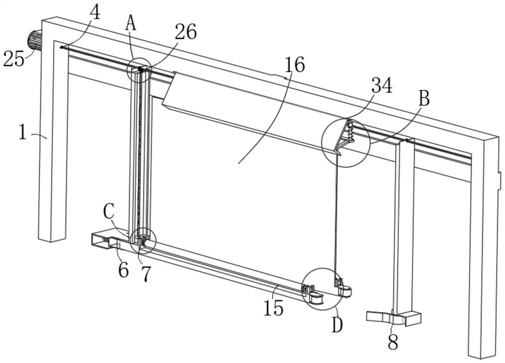
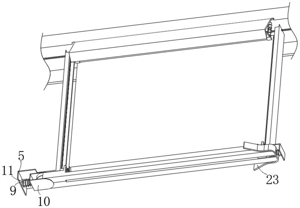
[0031] see figure 1 , figure 2 and Figure 5-Figure 8 , the present invention provides a relay parameter automatic adjustment machine for automatic debugging of relay shrapnel, including a work frame 1, two electric slide rails 2 are arranged on one side of the work frame 1, and the moving ends of the two electric slide rails 2 are respectively fixed Two adjustment frames 3 are arranged, and the inner side of the working frame 1 is provided with a driving mechanism 4, an active frame 5 and a passive frame, and the active frame 5 and the passive frame are installed on the two far ends of the two adjustment frames 3 respectively, and the active frame 5 An active assembly 6 is arranged inside, a working mechanism 7 is arranged outside the active assembly 6 , and a passive assembly 8 is arranged inside the passive frame.
[0032] The active assembly 6 comprises a movable telescopic rod 9, one end of which is fixed on the inside of the active frame 5, and the far end is provided...
Embodiment 2
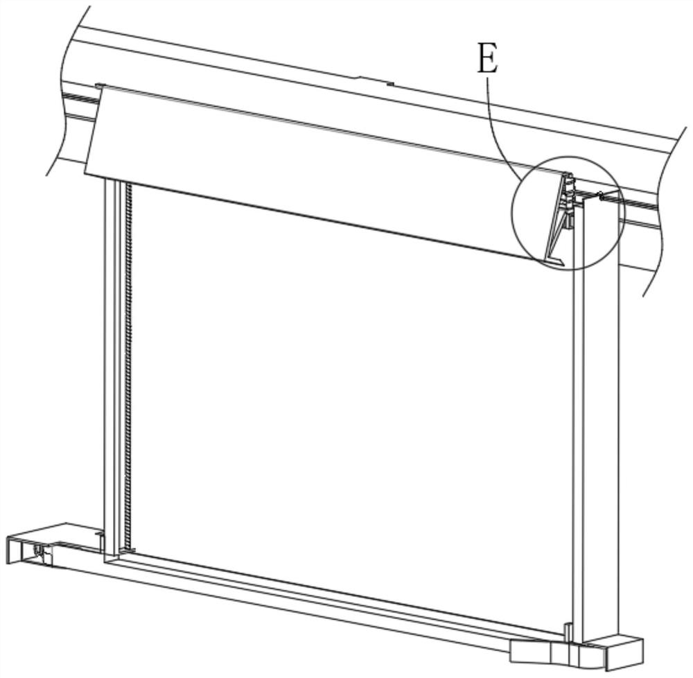
[0036] see image 3 , Figure 4 and Figure 9 , this embodiment further illustrates Embodiment 1. The present invention provides a relay parameter automatic adjustment machine for automatic debugging of relay shrapnel, including a working frame 1, and two electric slide rails 2 are arranged on one side of the working frame 1, two The moving ends of the electric slide rail 2 are respectively fixed with two adjustment frames 3, the inner side of the work frame 1 is provided with a driving mechanism 4, an active frame 5 and a passive frame, and the active frame 5 and the passive frame are installed on two adjustment frames respectively. At the far end of the frame 3, an active assembly 6 is provided inside the active frame 5, a working mechanism 7 is provided outside the active assembly 6, and a passive assembly 8 is provided inside the passive frame.
[0037] Wherein, the passive assembly 8 includes a movable telescopic rod 9, one end of the movable telescopic rod 9 is fixed o...
Embodiment 3
[0042] see Figure 5 , the present embodiment further illustrates embodiment 2. The present invention provides a relay parameter automatic adjustment machine for automatic debugging of relay shrapnel, including a working frame 1, and two electric slide rails 2 are arranged on one side of the working frame 1, and two The moving ends of the electric slide rail 2 are respectively fixed with two adjustment frames 3, the inner side of the work frame 1 is provided with a driving mechanism 4, an active frame 5 and a passive frame, and the active frame 5 and the passive frame are installed on two adjustment frames respectively. At the far end of the frame 3, an active assembly 6 is provided inside the active frame 5, a working mechanism 7 is provided outside the active assembly 6, and a passive assembly 8 is provided inside the passive frame.
[0043] Wherein, the control assembly 26 includes a control board 27, one side of the control board 27 is fixed on the upper end of the adjustm...
PUM
 Abstract
Description
Claims
Application Information
 - R&D
- Intellectual Property
- Life Sciences
- Materials
- Tech Scout
- Unparalleled Data Quality
- Higher Quality Content
- 60% Fewer Hallucinations
Browse by: Latest US Patents, China's latest patents, Technical Efficacy Thesaurus, Application Domain, Technology Topic, Popular Technical Reports.
© 2025 PatSnap. All rights reserved.Legal|Privacy policy|Modern Slavery Act Transparency Statement|Sitemap|About US| Contact US: help@patsnap.com


