Bus communication control circuit and control method thereof

A bus communication and control circuit technology, applied in the bus network, data exchange through path configuration, electrical components, etc., can solve problems such as equipment interference, increase the number of communication nodes, reduce the probability of interference, and improve bus utilization Effect

Active Publication Date: 2021-11-12
GREE ELECTRIC APPLIANCES INC
View PDF5 Cites 2 Cited by
  • Summary
  • Abstract
  • Description
  • Claims
  • Application Information

AI Technical Summary

Problems solved by technology

[0004] In view of this, the object of the present invention is to provide a bus communication control circuit and its control method to solve the problem of mutual interference between devices connected to the bus in the prior art

Method used


Image

  • Bus communication control circuit and control method thereof
  • Bus communication control circuit and control method thereof
  • Bus communication control circuit and control method thereof

Examples


Embodiment 1

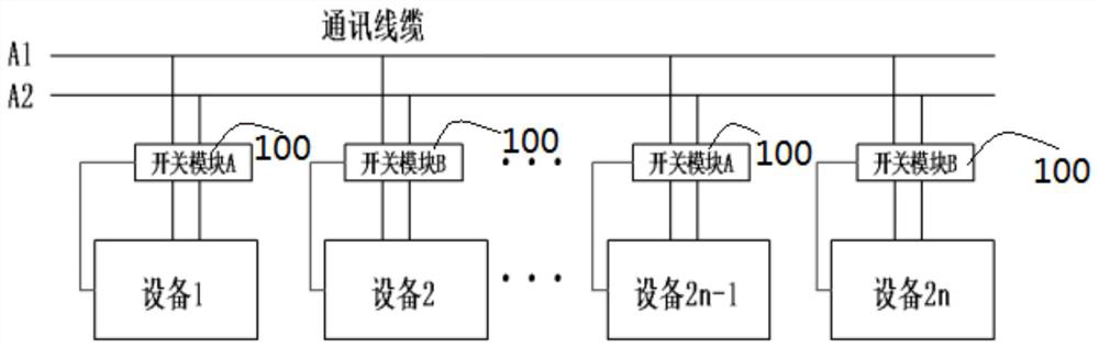
[0052] figure 1 is a schematic block diagram of a bus communication control circuit shown according to an exemplary embodiment, such as figure 1 As shown, the bus communication control circuit includes:

[0053] at least one switch module 100;

[0054] A switch module 100 is arranged between a device to be connected and the bus;

[0055] The switch module 100 is used for detecting the communication state of the device to be connected, and controlling the device to be connected to the bus or disconnected from the bus according to the communication state.

[0056] It can be understood that since one switch module 100 is disposed between a device to be connected and the bus, the number of switch modules 100 is the same as the number of devices to be connected. Each device to be connected is connected to the bus through its own switch module 100, and each device to be connected is independently controlled without interfering with each other, which improves the reliability of th...

Embodiment 2

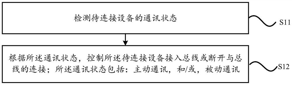
[0097] image 3 It is a flow chart of a control method for a bus communication control circuit shown according to an exemplary embodiment, as shown in image 3 As shown, the control method includes:

[0098] Step S11, detecting the communication status of the device to be connected;

[0099] Step S12. Control the device to be connected to connect to the bus or disconnect from the bus according to the communication status; the communication status includes: active communication and / or passive communication.

[0100] It can be understood that the technical solution provided by this embodiment controls whether the device to be connected is connected to the bus by detecting the communication state of the device to be connected, and according to the communication state of the device to be connected, compared with the prior art, all devices are always connected to the bus The connected technical solution, the technical solution provided by this embodiment, can allow the devices to...


PUM


Abstract

The invention relates to a bus communication control circuit and a control method thereof. The bus communication control circuit comprises at least one switch module; one switch module is arranged between one to-be-connected device and a bus; and the switch module is used for detecting the communication state of the to-be-connected equipment and controlling the to-be-connected equipment to be connected into the bus or disconnected from the bus according to the communication state. According to the technical scheme provided by the invention, the switch module is arranged between the to-be-connected equipment and the bus, and the to-be-connected equipment is controlled to be connected into the bus or disconnected from the bus by detecting the communication state of the to-be-connected equipment, so that compared with the technical scheme that all equipment is always connected with the bus in the prior art, according to the invention, the to-be-connected equipment can be accessed to the bus as required, so that the probability that the to-be-connected equipment is interfered by other equipment on the bus and the other equipment on the bus is interfered is reduced, and the communication reliability is improved.

Description

technical field [0001] The invention relates to the technical field of circuit design, in particular to a bus communication control circuit and a control method thereof. Background technique [0002] Any microprocessor must be connected to a certain number of components and peripherals, but if each component and each peripheral is directly connected to the CPU with a set of lines, the wiring will be complicated and even difficult to achieve. In order to simplify the hardware circuit design and simplify the system structure, a group of lines is commonly used, configured with an appropriate interface circuit, and connected to various components and peripherals. This group of shared connection lines is called a bus. The use of the bus structure facilitates the expansion of components and equipment, especially the development of a unified bus standard makes it easy to interconnect different devices. [0003] Bus communication (such as CAN bus, 485 bus, etc.) has the advantages ...

Claims


Application Information

Patent Timeline
Patent Type & Authority Applications(China)
IPC IPC(8): H04L12/40
CPCH04L12/40013
Inventor 李玉发刘泉洲叶铁英张亚国
Owner GREE ELECTRIC APPLIANCES INC
Why Eureka
Try Eureka