
Low-power-consumption constant-current starting LED driving power supply

A technology of LED drive and low power consumption, applied in the direction of electrical components, etc., can solve problems such as the influence of LED drive power supply start-up speed, fast start-up speed with large input current, and fast start-up speed with small input current, so as to improve user experience and reduce power consumption. Consumption, the effect of improving the startup speed

Pending Publication Date: 2021-11-12
XIAMEN CITY KELI ELECTRONICS
View PDF0 Cites 1 Cited by
  • Summary
  • Abstract
  • Description
  • Claims
  • Application Information

AI Technical Summary

Problems solved by technology

[0003] However, most of the current LED drive power supplies power to the control module by connecting several resistors with large resistance to the DC bus voltage and then connecting to the power supply terminal of the control module when starting up. However, when the DC bus voltage is full voltage When inputting, the start-up speed of the LED drive power supply will be affected; when the input voltage is large, the input current is large, the start-up speed is fast, and when the input voltage is small, the input current is small, the start-up speed is slow; The resistance value of the resistor can increase the startup speed, but when the resistance value of the resistor decreases, the power consumption on the resistor will increase, which will have an impact on the standby power consumption
[0004] In summary, the LED drive power supply in the prior art still needs to be further improved

Method used


Image

  • Low-power-consumption constant-current starting LED driving power supply
  • Low-power-consumption constant-current starting LED driving power supply
  • Low-power-consumption constant-current starting LED driving power supply

Examples


Embodiment Construction

[0045] The following will clearly and completely describe the technical solutions in the embodiments of the present invention with reference to the drawings in the embodiments of the present invention. Obviously, the described embodiments are preferred embodiments of the invention and should not be seen as excluding other embodiments. Based on the embodiments of the present invention, all other embodiments obtained by persons of ordinary skill in the art without creative efforts fall within the protection scope of the present invention.

[0046] In the claims, description and above-mentioned drawings of the present invention, unless otherwise clearly defined, the terms "first", "second" or "third" are used to distinguish different objects, not for Describe a specific order.

[0047] In the claims, specification and above-mentioned drawings of the present invention, unless otherwise clearly defined, for orientation words, such as using the terms "center", "transverse", "longit...


PUM


Abstract

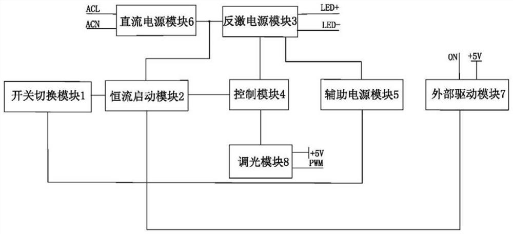
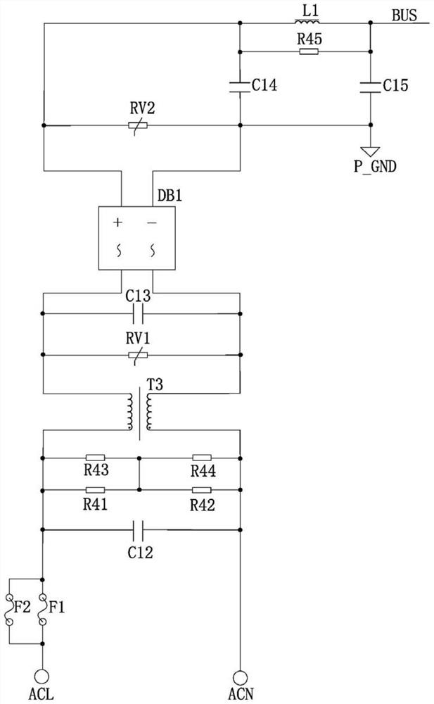
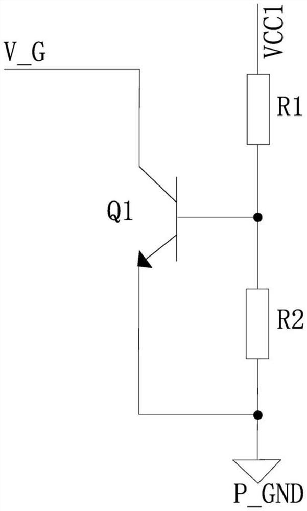
The invention discloses a low-power-consumption constant-current starting LED driving power supply. The driving power supply comprises a direct-current power supply module, a flyback power supply module, a control module, a constant-current starting module, an auxiliary power supply module, a switch switching module and a dimming module. The direct-current power supply module is used for converting alternating-current input into direct-current bus voltage; the power supply input end and the power supply output end of the flyback power supply module are respectively connected with a direct current bus voltage and an LED; the power supply end of the control module is used for receiving starting voltage, the signal receiving end is used for receiving external signals, and the signal output end is connected with the driving end of the flyback power supply module and controls the on-off of the flyback power supply module; the power input end of the constant-current starting module is connected with direct-current bus voltage, and the power output end is connected with the power end of the control module; and the switch switching module is used for pulling down the voltage of the first control end to turn off the constant current starting module when the flyback power supply module is started, so that low power consumption and quick starting are realized.

Description

technical field [0001] The invention relates to the technical field of LED power supplies, in particular to a low-power constant-current start-up LED drive power supply. Background technique [0002] With the improvement of people's living standards, people's requirements for quality of life are getting higher and higher. In the field of lighting, LED lights are widely used due to their energy-saving, durable and other characteristics. [0003] However, most of the current LED drive power supplies power to the control module by connecting several resistors with large resistance to the DC bus voltage and then connecting to the power supply terminal of the control module when starting up. However, when the DC bus voltage is full voltage When inputting, the start-up speed of the LED drive power supply will be affected; when the input voltage is large, the input current is large, the start-up speed is fast, and when the input voltage is small, the input current is small, the sta...

Claims


Application Information

Patent Timeline
Patent Type & Authority Applications(China)
IPC IPC(8): H05B45/385H05B45/50H05B45/345H05B45/36H05B45/10
CPCH05B45/385H05B45/50H05B45/345H05B45/36H05B45/10
Inventor 翁贵聪李俊需伍佼张志伟王其才徐进远
Owner XIAMEN CITY KELI ELECTRONICS
Learn More