Air inlet duct for nacelle of aircraft propulsion assembly

A propulsion component and air inlet technology, applied in the aviation field, can solve the problems of reducing the cabin, reducing the ability of the air inlet duct to capture air, reducing the air inlet duct, etc., to increase the flow rate, increase the air capture surface, and improve the distribution Effect

Pending Publication Date: 2021-11-12
SAFRAN AIRCRAFT ENGINES SAS
View PDF11 Cites 2 Cited by
  • Summary
  • Abstract
  • Description
  • Claims
  • Application Information

AI Technical Summary

Problems solved by technology

[0008] Furthermore, the current trend is to reduce the length of the nacelle and thus the length of the air inlet ducts, which reduces the ability of the air inlet ducts to capture air, in particular, under the aforementioned adverse conditions

Method used


Image

  • Air inlet duct for nacelle of aircraft propulsion assembly
  • Air inlet duct for nacelle of aircraft propulsion assembly
  • Air inlet duct for nacelle of aircraft propulsion assembly

Examples


Embodiment Construction

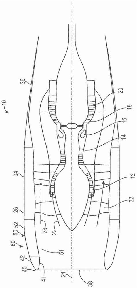
[0025] Propulsion assembly 10 includes an engine or turbine surrounded by nacelle 26 .

[0026] refer to figure 1 , the turbine is a two-flow turbine, and the two-flow turbine includes from upstream to downstream in the airflow direction: a low-pressure (LP) compressor 12, a high-pressure (HP) compressor 14, an annular combustion chamber 16, a high-pressure (HP) turbine 18 and a low-pressure (LP) turbine 20 , these define a flow channel for the primary airflow 22 .

[0027] The rotor of high pressure turbine 18 is integral with the rotor of high pressure compressor 14 to form a high pressure body, and the rotor of low pressure turbine 20 is integral with the rotor of low pressure compressor 12 to form a low pressure body. The rotor of each turbine rotates the rotor of the associated compressor about the longitudinal axis 24 by the thrust of gases from the combustion chamber 16 .

[0028] In the following description, the terms upstream and downstream refer to the flow of gas...


PUM


Abstract

The invention relates to an air inlet duct (60) for a nacelle (26) of an aircraft propulsion assembly (10). The duct (60) comprises an annular body (50) and an annular air inlet lip (40) comprising two coaxial annular walls (41, 42), respectively an inner wall (41) and an outer wall (42), the inner wall (41) defining part of an inner annular surface of the air inlet duct (60), and the outer wall (42) defining part of an outer annular surface of the air inlet duct (60). The air inlet duct (60) further comprises a control system (70) for axially translating the lip (40) relative to the body (50) from a first position in which the lip (40) is attached to the body (50) to a second position in which the lip (40) is axially spaced from the body (50). According to the invention, the duct (60) further comprises an annular row of grilles (90) fixed in translation to the lip (40), the annular row of grilles is configured to be housed within the body in the first position (50) and to extend from the body (50) in the second position such that an air flow (100) entering the air inlet duct (60) travels through the annular row of grilles.

Description

technical field [0001] The present invention relates to the field of aeronautics, and more particularly to air inlet ducts for nacelles of aircraft propulsion assemblies. Background technique [0002] In particular, the prior art includes documents US-A-3400902, US-A-4047911 and US-2014 / 127001. [0003] The propulsion assembly consists of a turbine-type engine surrounded by a nacelle. If the turbine is a twin-flow turbojet, the airflow traveling through the air inlet duct travels through the fan blades and is then divided into a primary airflow entering the turbine and a secondary airflow flowing around the turbine. [0004] The nacelle includes an air inlet duct, an intermediate structural member, and a downstream structural member connected together to form a secondary airflow channel. [0005] On the one hand, the air inlet duct comprises an air inlet lip arranged to enable optimum capture of the air required to supply the engine over the entire operating range of the e...

Claims


Application Information

Patent Timeline
Patent Type & Authority Applications(China)
IPC IPC(8): B64D33/02F02C7/04B64D29/00
CPCB64D33/02B64D29/00F02C7/042F05D2260/50F02C7/057
Inventor 昆汀·马蒂亚斯·伊曼纽尔·加诺德安东尼·埃利·海勒古亚奇尼古拉斯·约瑟夫·西尔文
Owner SAFRAN AIRCRAFT ENGINES SAS
Why Eureka
Try Eureka