
Detection equipment for automatic lathe and using method of detection equipment

A detection equipment and automatic lathe technology, applied in the field of lathe detection, can solve the problems of inability to adjust and move the device, inability to adjust the detection mechanism, single use structure, etc., and achieve the effects of increasing the detection range, convenient lighting, and excellent effects

Inactive Publication Date: 2021-11-16
江苏振宏智能科技有限公司
View PDF1 Cites 1 Cited by
  • Summary
  • Abstract
  • Description
  • Claims
  • Application Information

AI Technical Summary

Problems solved by technology

[0003] In the prior art, the patent with the authorized announcement number CN201720329468.4 discloses a device for automatic lathe detection of drill bit breakage, which can detect whether the drill bit is broken through an induction switch. The existing detection equipment for lathes has certain defects in use. Disadvantages, first of all, the device cannot be adjusted and moved conveniently during use, and the use structure is relatively simple, which is not conducive to people's use. In addition, the detection mechanism cannot be adjusted well when used. The range is small, which has brought certain adverse effects to people's use process. Therefore, we propose a detection device for automatic lathes and its use method

Method used


Image

  • Detection equipment for automatic lathe and using method of detection equipment
  • Detection equipment for automatic lathe and using method of detection equipment
  • Detection equipment for automatic lathe and using method of detection equipment

Examples


Embodiment 1

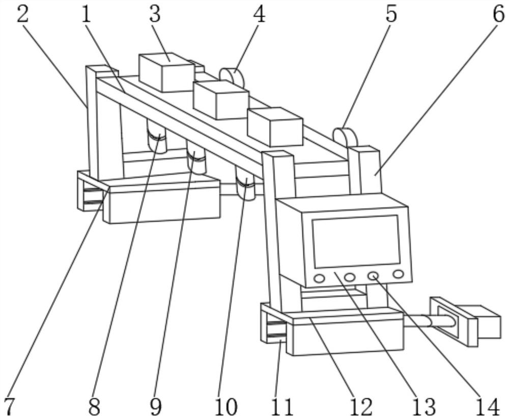
[0032] like figure 1 , 3 Shown, an automatic lathe with the sensing device, the device comprising a top plate, the top plate 1 is fixed to one end of the device is connected to mounting post One 2, apparatus 1 is fixed to the top plate and the other end connected to the mounting posts 6 II, One mounting post 2 One lower end fixedly attached to the positioning holder 7, the lower end of the mounting post II 6 II fixedly mounted positioning abutment 12, on the 2nd column 6 is mounted is attached to the outside of the control box 13, outer box 13 is attached to a control housing 14 to control , the upper end of the top plate unit 1 is mounted a drive mechanism 3, the lower end of the top plate unit 1 mounted One mounting rod 8, II and III mounting posts 9 the mounting bar 10.

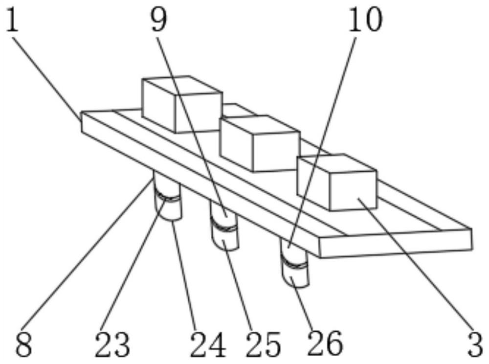
[0033] One mounting bar 8 is attached to the lower end of the temperature monitoring sensor 24, the lower end of the rod 9 II mounting position mounted condition monitoring probe 25, the lower end of the mount...

Embodiment 2

[0040] On the basis of the first example, if figure 1 , 2 , 4, with the sensing device for an automatic lathe, comprising a roof apparatus 1, the top end of the apparatus 1 is fixed to mounting post 2 is connected to One, the other end of the top plate 1 has a connecting device 6 II mounting posts, the mounting posts One 2 with a lower end fixedly mounted One positioning abutment 7, the lower end of the mounting post II 6 II fixedly mounted positioning abutment 12, on the 2nd column 6 is mounted is attached to the outside of the control box 13, the outer control box 13 is mounted a control Block 14, the upper end of the top plate unit 1 is mounted a drive mechanism 3, the lower end of the top plate unit 1 mounted One mounting rod 8, II and III mounting posts 9 the mounting bar 10.

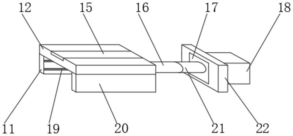
[0041] II positioning the positioning plate 15 is attached to mounting, II positioning abutment 12 is attached to the lower end of the slide plate 11 and II One slide plate 20, the slide plate 11 defin...

Embodiment 3

[0049] On the basis of the second embodiment, as figure 1 , 5 , 6, an automatic lathe with the sensing device, the device comprising a top plate 1, the top end of the apparatus 1 is fixed to mounting post 2 is connected to One, the other end of the top plate 1 has a connecting device 6 II mounting posts, the mounting posts One 2 with a lower end fixedly mounted One positioning abutment 7, the lower end of the mounting post II 6 II fixedly mounted positioning abutment 12, on the 2nd column 6 is mounted is attached to the outside of the control box 13, the outer control box 13 is mounted a control Block 14, the upper end of the top plate unit 1 is mounted a drive mechanism 3, the lower end of the top plate unit 1 mounted One mounting rod 8, II and III mounting posts 9 the mounting bar 10.

[0050] The control box 13 includes a central management module, a control module, power module, a temperature monitoring module, the position of the state monitoring module, working status monito...


PUM


Abstract

The invention discloses detection equipment for an automatic lathe and a using method of the detection equipment. The detection equipment comprises a device top plate, one end of the device top plate is fixedly connected with a first mounting column, the other end of the device top plate is fixedly connected with a second mounting column, a first positioning support is fixedly mounted at the lower end of the first mounting column, a second positioning support is fixedly mounted at the lower end of the second mounting column, and a controller is mounted on the outer side of the second mounting column. According to the detection equipment for the automatic lathe and the using method of the detection equipment, a movable mounting base, a multifunctional detection mechanism, an illumination mechanism and a central control module are arranged, the position of the device can be conveniently and better adjusted, the device can move, the detection range is enlarged, the temperature and working condition of the lathe and the position of a moving part can be conveniently monitored, illumination can be conveniently carried out on the working of the lathe, central management is facilitated, the automatic control effect is more excellent, and better use prospects are brought.

Description

Technical field [0001] The present invention relates to the detection lathe, and more particularly relates to an automatic lathe with a detection apparatus and method of use. Background technique [0002] Lathe with the sensing device is a support apparatus for the detection of lathe work, while the lathe machining of parts, the need for testing on the lathe itself, to prevent problems in the lathe can not be found in time and cause accidents, when using a lathe using detection device detects it, with the continuous development of technology, people are increasingly high requirements for the manufacturing process lathe with testing equipment. [0003] In the prior art, authorized announcement No. CN201720329468.4 patent discloses an apparatus for automatic lathes detect broken drill bit may be broken by the sensor switch detecting whether a bit, conventional lathe with the sensing device when using certain drawbacks, first of all, the time during use of the apparatus can easily b...

Claims


Application Information

Patent Timeline
Patent Type & Authority Applications(China)
IPC IPC(8): B23B25/00B23Q17/24
CPCB23B25/00B23Q17/2404B23Q17/2452
Inventor 张金富方英奎
Owner 江苏振宏智能科技有限公司
Learn More