Grinding equipment for interior of aluminum alloy hollow pipe for aerospace
An aerospace and aluminum alloy technology, which is applied in the field of internal grinding equipment of aluminum alloy hollow tubes for aerospace, can solve the problems of insufficient uniform grinding of aluminum alloy hollow tubes, poor grinding effect, and easy shaking of aluminum alloys, saving manpower. , Improve the effect of grinding, the effect of uniform grinding
- Summary
- Abstract
- Description
- Claims
- Application Information
AI Technical Summary
Problems solved by technology
Method used
Image

Examples
Embodiment 1
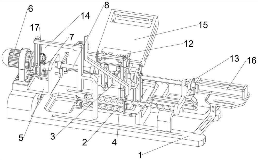
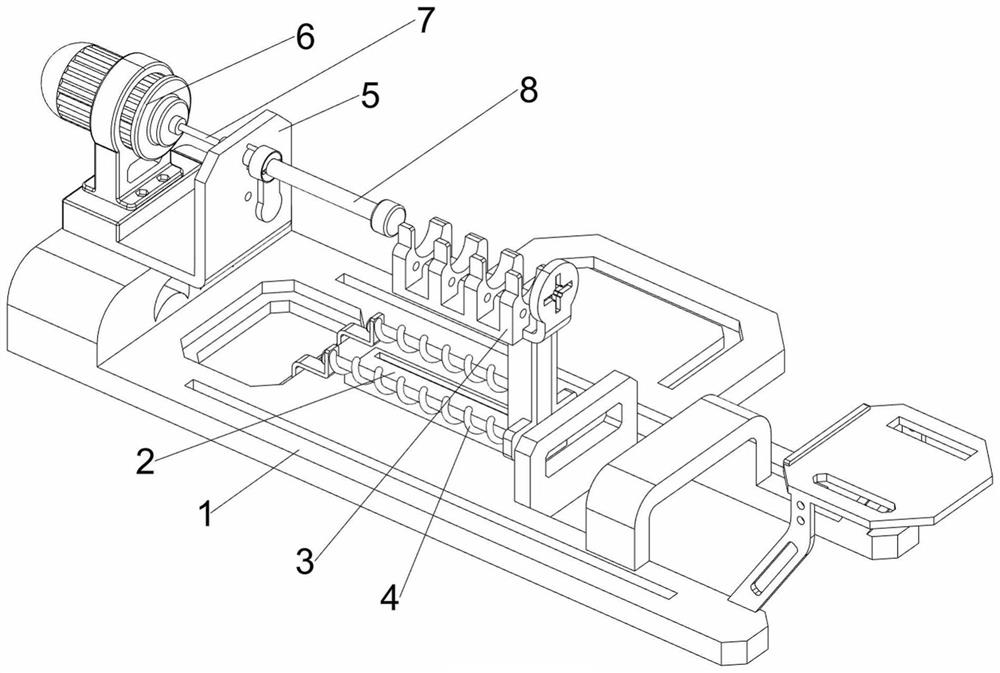
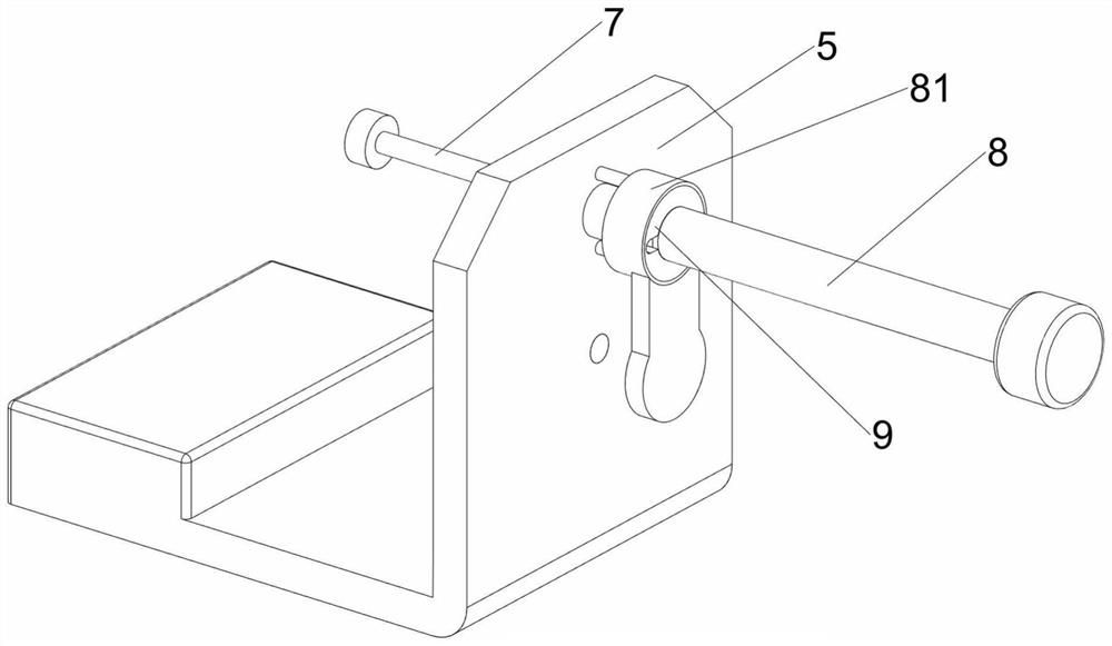
[0039] A kind of internal grinding equipment of aluminum alloy hollow tube for aerospace, such as Figure 1-8As shown, it includes a frame 1, a first guide rail 2, a material rack 3, a first spring 4, a support plate 5, a motor 6, a first rotating shaft 7, a grinding shaft 8, an annular sleeve 81, a fixed ring block 9, Connecting shaft 10, torsion spring 11, clamping mechanism 12 and pushing mechanism 13, the top of frame 1 is connected with first guide rail 2, and the first guide rail 2 is slidingly connected with material rack 3, and material rack 3 is connected with the second Two first springs 4 are connected between a guide rail 2, a support plate 5 is connected to the left side of the top of the frame 1, a motor 6 is installed on the support plate 5, and a first rotating shaft 7 is connected to the output shaft of the motor 6. A rotating shaft 7 is rotatably matched with the supporting plate 5, and an annular sleeve 81 is slidably connected to the top of the right side o...
Embodiment 2
[0045] On the basis of Example 1, such as figure 1 , Figure 9 and Figure 10 As shown, an extruding mechanism 14 is also included, and the extruding mechanism 14 includes a worm 141, a worm wheel 142, a second support plate 143, a second rotating shaft 144, a connecting rod 145, a third sliding frame 146 and a fourth guide rail 148, The first rotating shaft 7 is connected with a worm screw 141, the left side of the support plate 5 is connected with a second support plate 143, the second support plate 143 is rotatably connected with a second rotating shaft 144, and the rear side of the second rotating shaft 144 is connected with a worm wheel 142, Worm wheel 142 cooperates with worm screw 141, and frame 1 top front side is connected with the 4th guide rail 148, and the 4th guide rail 148 is slidably connected with the 3rd sliding frame 146, and the 3rd sliding frame 146 can support the first sliding frame 122 Now, the third sliding frame 146 cooperates with the second sliding...
Embodiment 3
[0050] On the basis of Example 2, such as figure 1 , Figure 13 and Figure 14 Shown, also include pusher mechanism 16, pusher mechanism 16 includes special-shaped bar 161, support shaft 162, missing gear 163, first connection rack 164, second connection rack 165 and cylinder 166, frame 1 top The right side is equipped with a cylinder 166, the telescopic rod of the cylinder 166 is connected with a special-shaped rod 161, the special-shaped rod 161 cooperates with the blanking valve 156, the telescopic rod of the cylinder 166 is in contact with the second sliding frame 131, and the front side of the third support plate 151 rotates The supporting shaft 162 is connected with the supporting shaft 162, the missing gear 163 is connected on the supporting shaft 162, the first connecting rack 164 is connected on the material blocking slider 154, the second connecting rack 165 is connected on the blanking valve 156, the first connecting tooth The bar 164 and the second connecting rac...
PUM
 Abstract
Description
Claims
Application Information
 - R&D
- Intellectual Property
- Life Sciences
- Materials
- Tech Scout
- Unparalleled Data Quality
- Higher Quality Content
- 60% Fewer Hallucinations
Browse by: Latest US Patents, China's latest patents, Technical Efficacy Thesaurus, Application Domain, Technology Topic, Popular Technical Reports.
© 2025 PatSnap. All rights reserved.Legal|Privacy policy|Modern Slavery Act Transparency Statement|Sitemap|About US| Contact US: help@patsnap.com