
Connecting device suitable for light railway vehicle

A railway vehicle and connecting device technology, which is applied in the direction of railway car body parts, traction devices, transportation and packaging, etc., can solve the problems of heavy weight, small rail vehicles that are not applicable, and large volume, so as to achieve small installation space and ease vibration effect

Pending Publication Date: 2021-11-16
苏州道卫轨道交通科技有限公司
View PDF0 Cites 0 Cited by
  • Summary
  • Abstract
  • Description
  • Claims
  • Application Information

AI Technical Summary

Problems solved by technology

At present, the commonly used vehicle coupling device is the coupler, but this kind of coupler has a complex structure, large volume and heavy weight, which is not suitable for small rail vehicles.

Method used


Image

  • Connecting device suitable for light railway vehicle
  • Connecting device suitable for light railway vehicle
  • Connecting device suitable for light railway vehicle

Examples


Embodiment 1

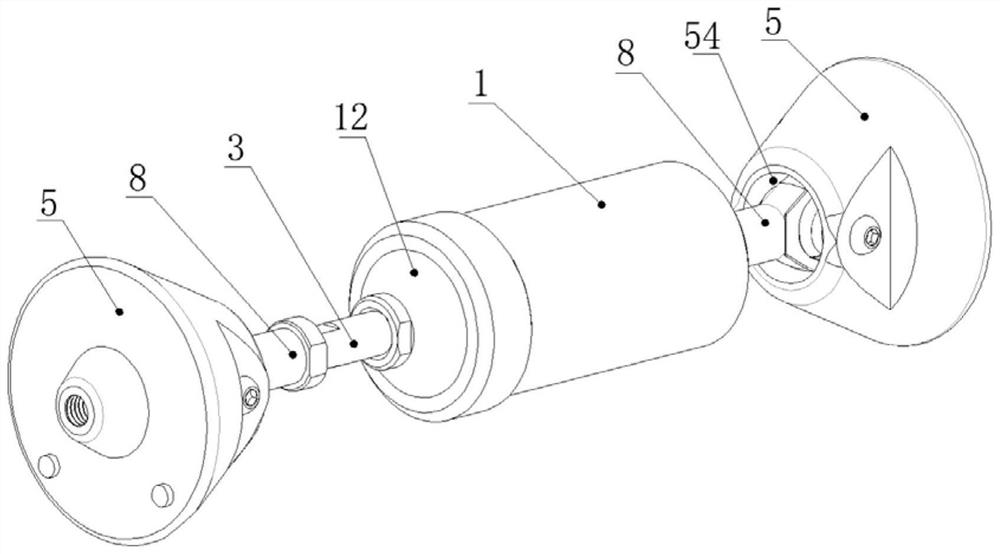
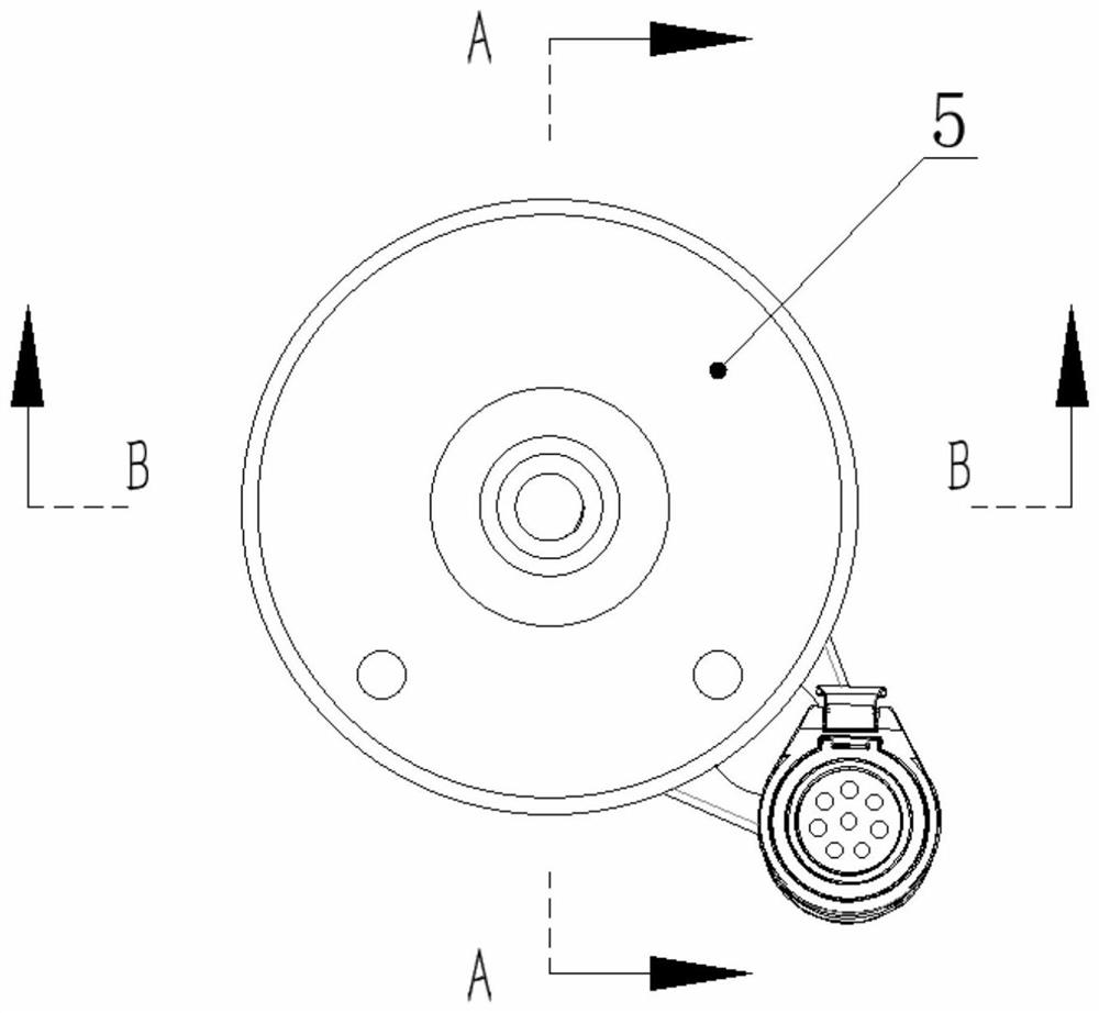
[0030] like Figure 1 to Figure 4 As shown, the present invention provides a connection device suitable for light railway vehicles, including a sleeve housing 1, which has a push-pull body 2 that can float left and right, and the left and right inner sides of the sleeve housing 1 Left and right buffer spring bodies 11 are mounted on the top between the wall and the push-pull body 2 respectively. It should be noted that, under no external force, the initial position of the push-pull body is in the middle of the sleeve housing. When an external force acts on the push-pull When the body is on the body, the push-pull body can move left or right. Once the external force disappears, under the elastic action of the left and right buffer springs, the push-pull body will return to the initial position.

[0031] It also includes a long pull rod 3, which is connected to the push-pull body 2, and a channel opening (not shown) for the long pull rod 3 to pass freely is provided on the side ...

Embodiment 2

[0043]Some special rail vehicles not only need to realize the mechanical connection between the front and rear adjacent vehicles, but also need to realize the electrical connection. The traditional method is to connect a cable between the two vehicles after the coupler is connected to the front and rear vehicles. This will increase the number of processes and reduce work efficiency. Therefore, in this embodiment, the combination of mechanical locking and electrical connection is chosen. Specifically, such as Figure 5 As shown, the connection device also includes a cable fixing bracket 6 connected to the sleeve housing 1 , a cable 7 is installed on the cable fixing bracket 6 , and the cable 7 has plugs 71 at both ends. In addition, it should be noted that the cable itself is flexible, and its length should not be too short, that is, it should not be shorter than the limit distance that can be produced by the two end connectors. The limit distance is when the push-pull body mo...


PUM


Abstract

The invention discloses a connecting device suitable for a light railway vehicle. The connecting device comprises a sleeve shell, a push-pull body capable of floating left and right is arranged in the sleeve shell, and a left buffer spring body and a right buffer spring body are installed between the left inner side wall and the right inner side wall of the sleeve shell and the push-pull body in an abutting mode, the connecting device comprises a short pull rod and a long pull rod which is connected to the push-pull body; and end part connectors, wherein the two end part connectors are respectively connected to the long pull rod and the short pull rod through a ball joint bearing. According to the connecting device, mechanical connection between two front and back adjacent vehicles is achieved through the end connectors, acting force generated when the front and back vehicles run is relieved through the push-pull body structural design capable of floating left and right, and the snakelike movement requirements of the front and back adjacent vehicles are met through the ball joint bearings in the end connectors, and vibration generated during operation is relieved. The connecting device is compact in structure, small in size and small in occupied installation space.

Description

technical field [0001] The invention relates to the technical field of vehicle connection, in particular to a connection device suitable for light railway vehicles. Background technique [0002] The vehicle connection device is an important part of a railway vehicle, and its main function is to connect two adjacent vehicles and transmit the force between the vehicles. For example, in rail vehicles, when the vehicles need to be rescued or connected, vehicle connection devices are often used to connect front and rear adjacent vehicles. A vehicle coupling device more commonly used at present is a coupler, but this coupler has a complex structure, a larger volume and a heavier weight, which is not suitable for small rail vehicles. Contents of the invention [0003] The object of the present invention is to provide a connecting device suitable for light railway vehicles, so as to solve the problems raised in the background art above. [0004] To achieve the above object, the ...

Claims


Application Information

Patent Timeline
IPC IPC(8): B61G9/04B61G9/20
CPCB61G9/04B61G9/20
Inventor 张国富许唯杰
Owner 苏州道卫轨道交通科技有限公司
Learn More