
Wind power tower drum

A technology for wind power towers and towers, which is applied to wind turbine components, wind turbines, mechanical equipment, etc., can solve problems such as single function, influence on wind energy utilization, and loosening of joints connected to each other, so as to ensure normal operation, Extends service life and reduces vibration

Inactive Publication Date: 2017-01-25
尊领科技集团有限公司
View PDF0 Cites 1 Cited by
  • Summary
  • Abstract
  • Description
  • Claims
  • Application Information

AI Technical Summary

Problems solved by technology

In the high temperature season, the ambient temperature of the wind farm becomes higher, and the temperature rises when the inverter, reactor and transformer work, and the heat cannot be dissipated in time, which affects the utilization of wind energy; The impact of major earthquakes or earthquakes will cause slight shaking, and the joints will become loose after a long time. When there is a thunderstorm, the wind power tower on the high mountain is most likely to cause lightning strikes. If there is no lightning protection device, the wind power tower will be greatly reduced. service life
The heat dissipation device for the existing wind power tower itself includes a tower made of closed steel plates, a fan is installed on the top of the tower, and an air supply unit is installed on the side of the tower to send the wind blown by the fan to the bottom of the tower. The upper opening of the air supply pipe is connected to the outlet of the fan, and the lower opening of the air supply pipe faces the heating element that needs to be dissipated. This device can achieve the effect of heat dissipation, but it can only solve the heat dissipation problem. It has a single function and cannot meet the needs of the market. The Many Needs of Wind Power Towers

Method used


Image

  • Wind power tower drum
  • Wind power tower drum

Examples


Embodiment

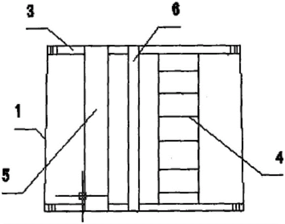
[0014] Example: see attached figure 1 , 2 , The wind power tower is provided with a tower body, and the tower body is composed of several sections of steel cones 1 connected end to end by several fixing bolts 2 in turn, and both ends of the cones are welded with steel joints. Lan 3, the tower body is provided with 3 sections of base ring steel cones, 3 sections of steel cones for the lower section of the tower, 4 sections of steel cones for the middle section of the tower, and 3 sections of steel cones for the upper section of the tower. Among the steel cones of the 4-section middle section of the tower, there is 1 section of middle and lower steel cones and 3 sections of middle and upper steel cones; the maximum diameter of the bottom of the tower body is 4>4200mm, and the minimum diameter of the top is (i>3005mm; The deviation angle between the top center of the tower body and the bottom center of the tower body and the ideal center line does not exceed 0.3 degrees, and the...


PUM

PropertyMeasurementUnit
The maximum diameteraaaaaaaaaa

Abstract

The invention relates to a wind power tower drum. The wind power tower drum is provided with a tower drum body. The tower drum body is formed by sequentially connecting multiple sections of steel conical barrels into a whole end to end through multiple fixing bolts. Steel flanges are welded to the two ends of the steel conical barrels. The tower drum body is provided with three sections of basic ring steel conical barrels, three sections of lower section tower frame steel conical barrels, fourth sections of middle section tower frame steel conical barrels and three sections of upper section tower frame steel conical barrels. A section of lower middle steel conical barrel and three sections of upper middle steel conical barrels are included in the four sections of middle section tower frame steel conical barrels. The wind power tower drum is suitable for wind power generation, and has the advantages of being scientific in design, reasonable in structure, high in wind-resisting capacity, long in service life, good in anticorrosion effect and high in wind energy utilization rate.

Description

technical field [0001] The invention belongs to the field of wind power generation equipment, in particular to a wind power tower. Background technique [0002] Wind energy is a clean, safe, and renewable green energy. The use of wind energy has no pollution to the environment, no damage to the ecology, good environmental and ecological benefits, and is of great significance to the sustainable development of human society. [0003] At present, the domestic wind power industry technology is gradually mature, and wind power towers are widely used in coastal areas, mountains, plains and other places with sufficient wind energy. It cannot be installed, or the quality cannot be guaranteed after installation, which increases the maintenance cost and causes a waste of wind energy. [0004] The vast majority of wind power towers are connected in sections, and the end of each section has a flange welded with the tower body. The connection between the sections is to lock the two flan...

Claims


Application Information

Patent Timeline
IPC IPC(8): F03D11/04
Inventor 不公告发明人
Owner 尊领科技集团有限公司
Learn More