Pressure balance system

A technology of balance and pressure, which is applied in the measurement of fluid pressure, the measurement of pressure difference between multiple valves, and the measurement of fluid pressure through electromagnetic components, etc. It can solve the problems of affecting the accuracy of the sensor, the large volume of the pressure stabilizing chamber, and the consumption of silicone oil. , to achieve the effect of reducing unbalance, improving accuracy and reducing the use of

Pending Publication Date: 2021-11-16
CHONGQING WECAN PRECISION INSTR
View PDF1 Cites 0 Cited by
  • Summary
  • Abstract
  • Description
  • Claims
  • Application Information

AI Technical Summary

Problems solved by technology

However, there are still some problems with this structure
First of all, the volume of the pressure stabilizing chamber is large, consumes more silicone oil, increases the cost, and brings challenges to the assembly and sealing between the cover body and the pressure induction seat
In addition, in order to simplify the structure, in the actual design, the pressure stabilizing chamber outside the sensor will be connected with one of the pressure transmitting chambers to ensure that the pressure inside and outside the sensor changes synchronously. As a result, the pressure of the silicon oil in the pressure transmission chamber on the side connected to the pressure stabilization chamber changes significantly on the measuring diaphragm, which affects the accuracy of the sensor

Method used


Image

  • Pressure balance system
  • Pressure balance system
  • Pressure balance system

Examples


Embodiment Construction

[0046] The present invention will be further described below in conjunction with embodiment and accompanying drawing.

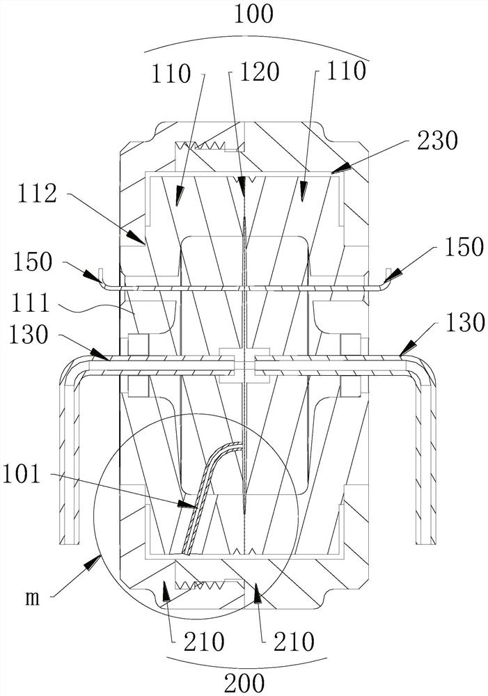
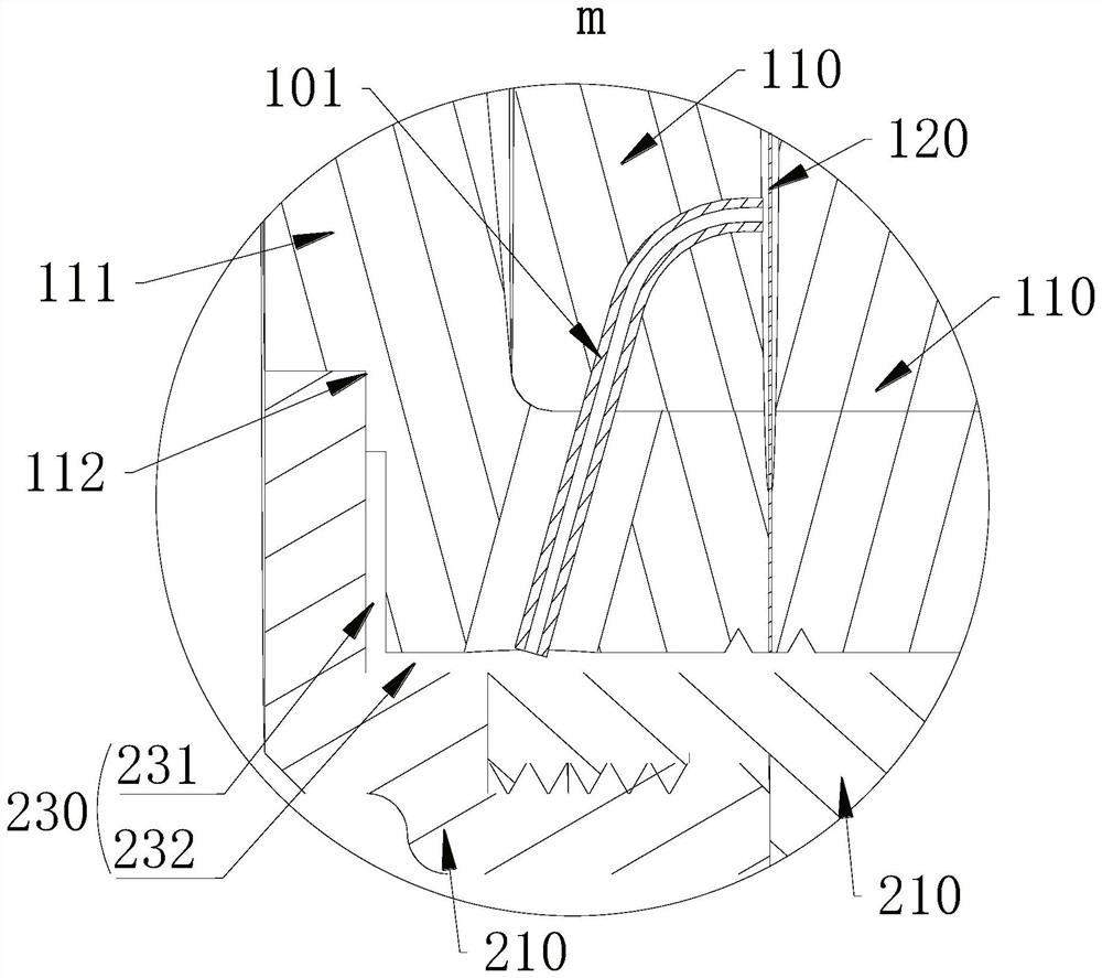
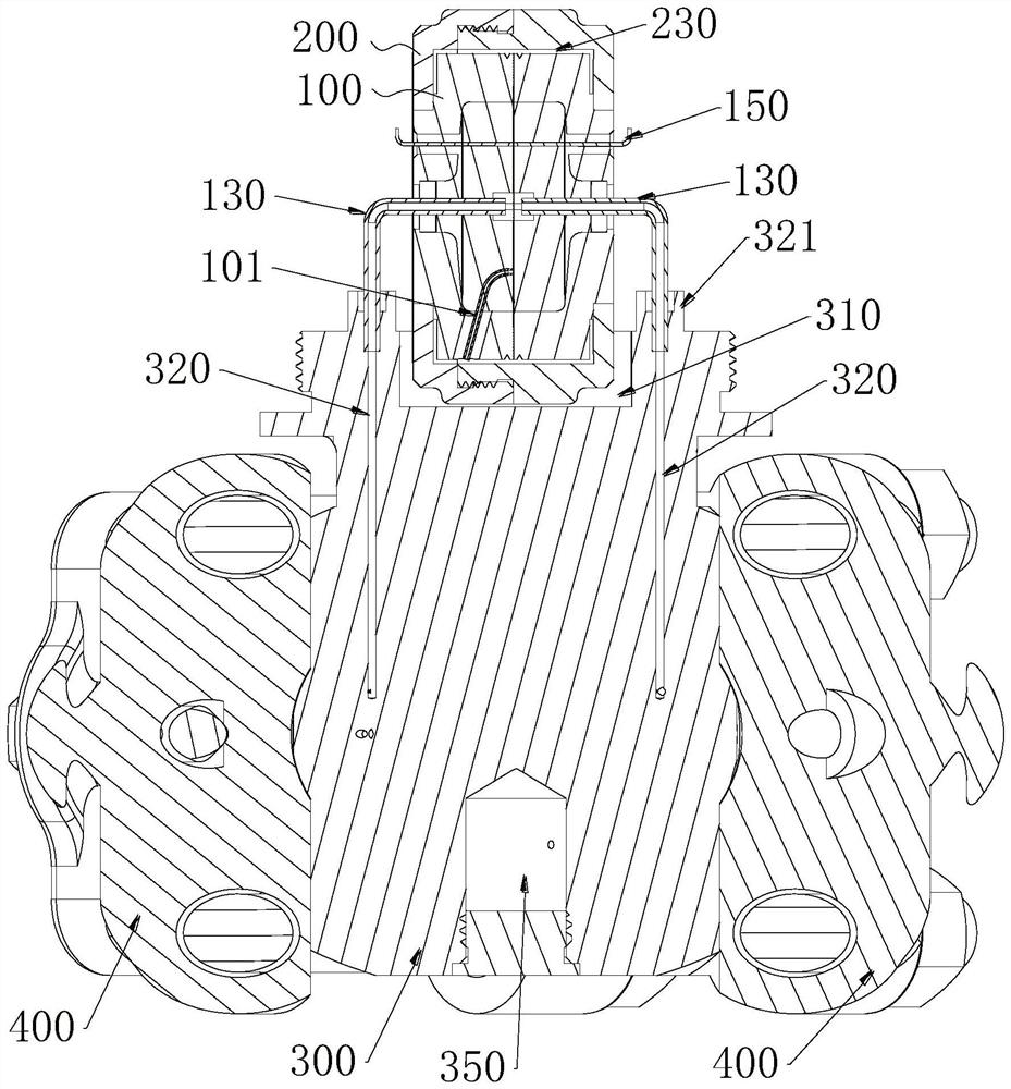
[0047] like Figure 1~3 As shown, a pressure balance system includes a diaphragm pressure sensor 100. The diaphragm pressure sensor 100 includes two diaphragm seats 110 facing oppositely, and a measuring diaphragm is interposed between the two diaphragm seats 110. The two diaphragm seats 110 are welded to the edge of the measuring diaphragm 120, and the measuring diaphragm 120 and the two diaphragm seats 110 respectively enclose a closed pressure transmission cavity. The outer cover of the diaphragm pressure sensor 100 is provided with a closed voltage stabilizing box 200, and there is a closed cavity between the inner wall of the stabilizing box 200 and the outer wall of the diaphragm pressure sensor 100, and the cavity surrounds the The outer wall of the diaphragm pressure sensor 100 is described above, and the cavity forms a pressure-stabilizing cavity 23...


PUM


Abstract

The invention discloses a pressure balance system which comprises a diaphragm type pressure sensor, two pressure transmitting cavities separated from each other are arranged in the diaphragm type pressure sensor, a closed pressure stabilizing box covers the diaphragm type pressure sensor, and a closed cavity is formed between the inner wall of the pressure stabilizing box and the outer wall of the diaphragm type pressure sensor, the outer wall of the diaphragm type pressure sensor is wrapped by the cavity, the cavity forms a pressure stabilizing cavity, a balance flow channel penetrates through the shell of the diaphragm type pressure sensor, and one pressure transmitting cavity is communicated with the pressure stabilizing cavity through the balance flow channel. The diaphragm type pressure sensor has the beneficial effects that through the compact and ingenious structural design, the use of a liquid pressure transmission medium is greatly reduced while the balance of the internal and external pressure of the diaphragm type pressure sensor is ensured, meanwhile, the unbalance of the pressure in the two pressure transmission cavities of the sensor caused by temperature change is remarkably reduced, and the precision of the sensor is improved.

Description

technical field [0001] The invention relates to a pressure measuring device, in particular to a pressure balance system of the pressure measuring device. Background technique [0002] A type of flow meter used to detect fluid flow. The detection principle is to detect the pressure values ​​at two different points on the fluid flow path. Since the pressure values ​​at these two points are different, the fluid flow can be calculated. The main body of this type of flowmeter is a fluid pressure detection device, and the core detection element of the fluid pressure detection device is a diaphragm pressure sensor. The diaphragm pressure sensor converts two pressure signals at different positions of the fluid into the change of the capacitance signal, and then the detection circuit at the back end processes the change of the capacitance signal to obtain the differential pressure value of the applied pressure. [0003] The diaphragm pressure sensor includes two disc-shaped diaphrag...

Claims


Application Information

Patent Timeline
Patent Type & Authority Applications(China)
IPC IPC(8): G01L19/00G01L19/06G01L9/00G01L9/12G01L13/06G01L13/02
CPCG01L19/00G01L19/06G01L9/0072G01L9/12G01L13/06G01L13/025
Inventor 唐田朱建刘庆杨小华
Owner CHONGQING WECAN PRECISION INSTR
Why Eureka
Try Eureka