Vision-based unmanned rotorcraft course calibration system and method in tunnel environment

A technology of unmanned rotor and tunnel environment, applied in the field of visual measurement, can solve the problems of being susceptible to interference, limited application scenarios, and limited ranging range of ultrasonic sensors, etc., to achieve the effect of ensuring safe flight, simple implementation, and easy calibration

Pending Publication Date: 2021-11-16
JIANGSU ELECTRIC POWER CO
View PDF3 Cites 0 Cited by
  • Summary
  • Abstract
  • Description
  • Claims
  • Application Information

AI Technical Summary

Problems solved by technology

This method uses an ultrasonic sensor for distance measurement. The distance measurement range of the ultrasonic sensor is limited and is easily interfered. The application scenarios of the positioning device and method are limited, and there are certain deficiencies.

Method used


Image

  • Vision-based unmanned rotorcraft course calibration system and method in tunnel environment
  • Vision-based unmanned rotorcraft course calibration system and method in tunnel environment
  • Vision-based unmanned rotorcraft course calibration system and method in tunnel environment

Examples


Embodiment Construction

[0059] The application will be further described below in conjunction with the accompanying drawings. The following examples are only used to illustrate the technical solutions of the present invention more clearly, but not to limit the protection scope of the present application.

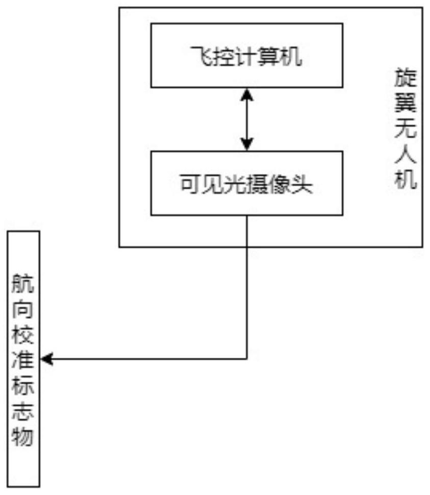
[0060] Such as figure 1 , the vision-based heading calibration system for rotor UAVs in tunnel environments includes: visible light cameras, heading calibration markers, and flight control computers.

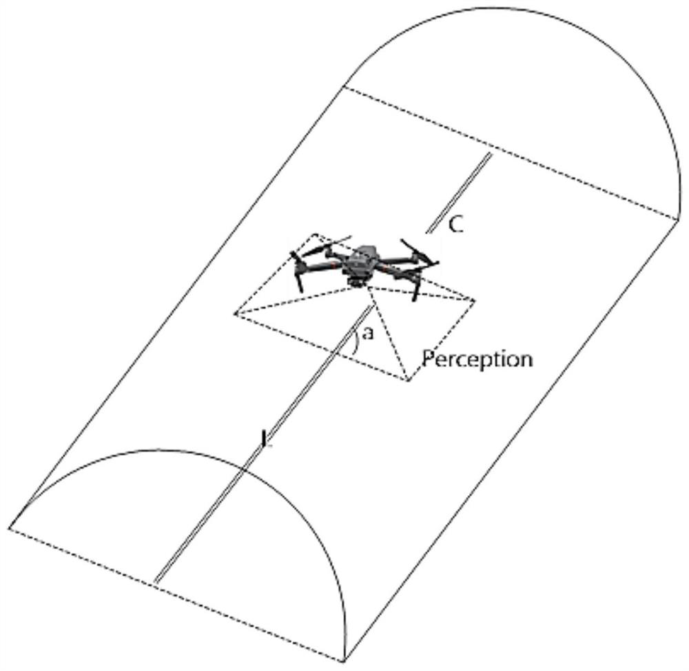
[0061] The heading calibration marker is set at the center of the tunnel floor along the radial direction of the tunnel; figure 2 , the heading calibration marker L is a high-contrast marking line, the width of which is not less than 5 cm, and the length is consistent with the radial length of the tunnel.

[0062] It is worth noting that the size of the course calibration marker used in the preferred embodiment of the present invention is a non-limiting preferred choice, and those skilled in the a...


PUM

PropertyMeasurementUnit
Widthaaaaaaaaaa

Abstract

The invention discloses a vision-based unmanned rotorcraft course calibration system and method in a tunnel environment, and the system comprises a visible light camera, a course calibration marker and a flight control computer, the visible light camera is installed right below an unmanned rotorcraft, and the flight control computer is carried in the unmanned rotorcraft; and after the unmanned rotorcraft takes off, the flight control computer controls the visible light camera to align with the course calibration marker for image acquisition, and the flight control computer identifies the acquired image based on a visual identification algorithm and controls the view field center line of the visible light camera to align with the course calibration marker based on a flight control algorithm. In a narrow tunnel environment, only the high-contrast identification line located in the center of the tunnel needs to be measured, and through real-time simple image processing, the flight line of the aircraft is corrected in real time, and the length direction of the tunnel is aligned; and implementation is simple, calibration is easy, and safe flight of the unmanned aerial vehicle can be accurately guaranteed.

Description

technical field [0001] The present invention relates to the technical field of visual measurement, and more particularly, to a vision-based heading calibration system and method for a rotor UAV in a tunnel environment. Background technique [0002] In recent years, rotor UAVs have developed rapidly. Due to their stable flight, easy control, low noise, and low safety hazards, they are more and more used in power inspections, especially in cable tunnel environments. more. [0003] In the existing technology, the heading calibration of the rotor UAV in the tunnel environment cannot be realized by using inertial components and satellites, and it relies on the magnetic compass for heading perception, which is very susceptible to interference in the cable tunnel environment, which will seriously affect the UAV. Trajectory control accuracy of hovering and maneuvering flight, leading to serious accidents. [0004] In the prior art, using machine vision to locate the rotor UAV, esp...

Claims


Application Information

Patent Timeline
IPC IPC(8): G05D1/08G05D1/10
CPCG05D1/0808G05D1/106
Inventor 何光华王永强黄薛凌徐雅惠张志坚卞栋徐骏何建益施子凡张伟
Owner JIANGSU ELECTRIC POWER CO
Why Eureka
Try Eureka