Broadband series-feed sparse array antenna unit

An array antenna and antenna unit technology, which is applied to antennas, antenna arrays, specific array feeding systems, etc., can solve problems such as inability to meet the system, and achieve the effect of reducing side lobes, reducing equivalent dielectric constant, and facilitating integration

Inactive Publication Date: 2021-11-16
成都雷电微力科技股份有限公司
View PDF6 Cites 1 Cited by
  • Summary
  • Abstract
  • Description
  • Claims
  • Application Information

AI Technical Summary

Problems solved by technology

The commonly used forms of one-dimensional phase-scanned array antenna elements include waveguide slots, microstrip patches, and substrate in

Method used


Image

  • Broadband series-feed sparse array antenna unit
  • Broadband series-feed sparse array antenna unit
  • Broadband series-feed sparse array antenna unit

Examples


Embodiment 1

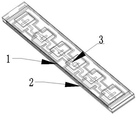
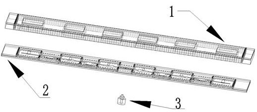
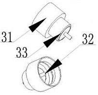
[0033] Such as figure 1 , figure 2 As shown, the broadband series-fed sparse array antenna unit includes antenna radiation layer 1, antenna feed layer 2 and SMP structure 3. SMP structure 3 is a radio frequency connection structure, which belongs to a waveguide to stripline transition structure. SMP Structure 3 can be replaced by other waveguide-to-stripline transition structures. The SMP structure 3 is connected to the antenna feed layer 2 , and the antenna feed layer 2 is in a coupling relationship with the antenna radiation layer 1 . The radio frequency signal is fed into the stripline conduction strip 22 of the antenna feed layer 2 through the SMP structure 3, and then divided into two paths by a power splitter to feed each antenna patch on the antenna radiation layer 1 respectively. . The signal on the stripline conduction strip 22 is coupled to the antenna patch of the antenna radiation layer 1 through the "one" slot 21 on the upper ground 25 of the antenna feed laye...

Embodiment 2

[0041] This embodiment discloses another wide-band series-fed sparse array antenna unit, which has roughly the same design as that of Embodiment 1, the only difference being that the air cavity 11 (cross section) is circular.

Embodiment 3

[0043] This embodiment discloses another broadband serial-fed sparse array antenna unit, which is roughly the same in design as the above-mentioned embodiment, the only difference is that in this embodiment, the power divider designed at the SMP matching part 221 is not A power divider divided into two, but a power divider divided into three or four.


PUM


Abstract

The invention discloses a broadband series-feed sparse array antenna unit, which comprises an antenna feed part and an antenna radiation part, wherein the antenna feed part comprises an SMP structure, a strip line matching adjustment and phase adjustment part and metalized isolation columns around a strip line. The antenna radiation part comprises a dielectric layer of the antenna, a radiation patch of the antenna, a parasitic patch and a metallization isolation column. A radio frequency signal is fed into a strip line in the antenna feed layer structure through the SMP structure, the strip line is subjected to one-to-two power distribution, the amplitude is equal, the phase difference is 180 degrees, the radio frequency signal is coupled to an antenna patch in the antenna radiation layer structure through a linear gap in the upper layer ground of the strip line and an air cavity, and radiation of radio frequency energy is achieved. The average distance of the plurality of antenna units is greater than half wavelength of the antenna under the working frequency, and the layout of the antenna patch adopts a comprehensive algorithm of an antenna pattern, so that lobe deletion of the antenna can be prevented, the gain of the antenna can be improved, and the side lobes of the antenna can be reduced.

Description

technical field [0001] The invention relates to the technical field of phased array antennas, in particular to a broadband series-fed sparse array antenna unit. Background technique [0002] Phased array antennas are widely used in radar and wireless communication fields because of their advantages such as fast beam scanning, flexible beamforming, and high reliability. The one-dimensional phase-scanned array antenna has the advantages of a phased array antenna, and the other dimension adopts a mechanical scanning method, which can greatly reduce the number of channels of the transceiver module, and the cost of the array antenna is controlled. It is widely used in various radar and communication products. The commonly used forms of one-dimensional phase-scanned array antenna elements include waveguide slots, microstrip patches, and substrate integration slots, etc., but they are often limited by factors such as antenna bandwidth, gain, and weight, which cannot meet the needs...

Claims


Application Information

Patent Timeline
IPC IPC(8): H01Q1/50H01Q1/38H01Q21/00
CPCH01Q1/50H01Q1/38H01Q21/0006
Inventor 邓金峰丁卓富阴明勇周沛翰薛伟
Owner 成都雷电微力科技股份有限公司
Why Eureka
Try Eureka