Low-temperature industrial toxic waste gas denitration equipment

A denitrification and industrial technology, applied in the field of denitrification equipment for low-temperature industrial toxic waste gas, can solve the problem of external discharge, and achieve the effect of avoiding being difficult to be used

Pending Publication Date: 2021-11-19
赖汉龙
View PDF0 Cites 0 Cited by
  • Summary
  • Abstract
  • Description
  • Claims
  • Application Information

AI Technical Summary

Problems solved by technology

[0003] Because the denitrifier for low-temperature industrial toxic waste gas dissolves and absorbs the oxidized nitrate substances through the alkaline solution inside the denitrification cylinder, but the outlet pipe is located above the liquid level of the alkaline solution, so some nitrate substances inside the toxic gas will be too late When it is absorbed by alkaline solution, it is directly discharged from the exhaust pipe

Method used


Image

  • Low-temperature industrial toxic waste gas denitration equipment
  • Low-temperature industrial toxic waste gas denitration equipment
  • Low-temperature industrial toxic waste gas denitration equipment

Examples


Embodiment 1

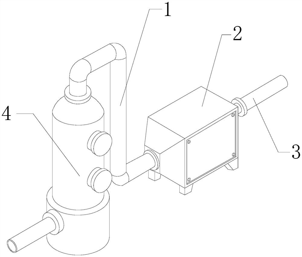
[0028] For example figure 1 -example Figure 5 Shown:

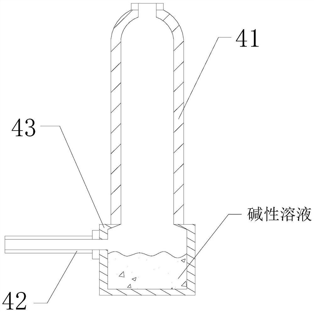
[0029] The present invention provides a denitrification device for low-temperature industrial toxic waste gas. The air pipe 3 is connected to the rear end flange of the oxidation chamber 2, and the top of the denitration chamber 4 is connected to the air guide pipe 1; the denitration chamber 4 includes a cylinder body 41, an absorption chamber 42, and an air outlet pipe 43. Fitted with the left side of the air outlet pipe 43 , the upper surface of the air outlet pipe 43 is welded to the bottom of the cylinder 41 .

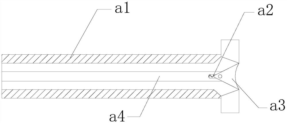
[0030] Wherein, the absorption bin 42 includes an outer tube a1, a reset bar a2, a sliding block a3, and a middle solid rod a4, and the reset bar a2 is installed between the inner wall of the sliding block a3 and the middle solid bar a4, and the sliding block a3 Engaging with the inside of the solid rod a4, the solid rod a4 penetrates the inner position of the outer tube a1, through the extrusion of the sli...

Embodiment 2

[0036] For example Image 6 -example Figure 9 Shown:

[0037] Wherein, the air outlet pipe 43 includes a blade c1, a frame c2, a bottom block c3, and a rotating shaft c4. The blade c1 is fixed on the side of the rotating shaft c4 near the upper end. The bottom fits together, the rotating shaft c4 is engaged with the inside of the bottom block c3, and the upper surface of the blade c1 has an inclined surface structure, and the blade c1 can drive the rotating shaft c4 along the The bottom block c3 rotates.

[0038]Wherein, the blade c1 includes a combination plate c11, a weight reduction cavity c12, and a guide groove c13, the combination plate c11 is fixed on the upper surface of the guide groove c13, and the weight reduction cavity c12 penetrates the inner position of the combination plate c11, The weight reducing cavity c12 has a hollow structure, and the weight reducing cavity c12 can reduce the overall weight of the connecting plate c11, so that the object can be rotate...


PUM


Abstract

The invention discloses low-temperature industrial toxic waste gas denitration equipment which structurally comprises a gas guide pipe, an oxidation bin, a gas inlet pipe and a denitration cylinder; the oxidation bin is fixed to the rear end of the gas guide pipe, the gas inlet pipe is connected with a flange at the rear end of the oxidation bin, the top of the denitration cylinder is connected with the gas guide pipe, gas without nitrate substances extrudes a sliding block, and the sliding block can slide leftwards along a middle fixing rod, so that gas can be exhausted outwards through the space between the sliding block and the inner wall of an outer pipe; and through the process, when the sliding block is extruded to slide leftwards, time can be won for an alkaline solution to absorb nitrate substances; and through thrust generated by poisonous gas entering the denitration cylinder from top to bottom on the upper surfaces of blades, the blades can drive a rotating shaft to rotate along a bottom block, so that an outer swing plate can stir an alkaline solution along with rotation of a rod body under the cooperation of an outer convex block.

Description

technical field [0001] The invention relates to the technical field of industrial harmful waste gas control, in particular to a denitrification device for low-temperature industrial toxic waste gas. Background technique [0002] The denitrification device for toxic waste gas in low temperature industry is mainly used for denitrification treatment of toxic gas produced in low temperature industry. By introducing the toxic gas into the oxidation chamber for oxidation, and then introducing the oxidized gas into the denitrification cylinder, the denitrification cylinder The alkaline solution inside can dissolve and absorb the nitrates inside the toxic gas. Based on the above description, the inventors found that the existing denitrification equipment for low-temperature industrial toxic waste gas mainly has the following deficiencies, for example: [0003] Because the denitrifier for low-temperature industrial toxic waste gas dissolves and absorbs the oxidized nitrate substances...

Claims


Application Information

Patent Timeline
Patent Type & Authority Applications(China)
IPC IPC(8): B01D53/78B01D53/56
CPCB01D53/78B01D53/56
Inventor 赖汉龙
Owner 赖汉龙
Why Eureka
Try Eureka