
Bearing inner and outer ring synchronous oil immersion device for machining

A technology of mechanical processing, inner and outer rings, applied to the device and coating of the surface coating liquid, can solve the problems of unsatisfactory oil rejection, bearing collision, complicated operation, etc., to achieve the best oil rejection effect and reduce labor intensity , The effect of simplifying the operation process

Active Publication Date: 2021-11-19
南通腾华新材料科技有限公司
View PDF8 Cites 0 Cited by
  • Summary
  • Abstract
  • Description
  • Claims
  • Application Information

AI Technical Summary

Problems solved by technology

[0004] In the actual use of this device, although the problem of uniform oiling of the inner ring, outer ring and rollers has been solved, after use, personnel are required to manually remove the oil-immersed bearing from the oil, and then place it in the In the oil throwing frame, it is cumbersome to take it out again after shaking the oil, and it will cause more oil on the hands of the staff, and more bearings will be piled up in the oil throwing frame , not only is it easy to cause collisions between bearings and damage, but also due to the structural characteristics of the bearing itself, when it is placed horizontally and the oil is thrown by centrifugal force, only the oil on the outer surface can be thrown off, while the oil on the outer ring and inner The oil accumulated between the rings and the inner ring, under the action of centrifugal force, a large part of the oil will still be blocked, and the effect of oil rejection is not ideal.

Method used


Image

  • Bearing inner and outer ring synchronous oil immersion device for machining
  • Bearing inner and outer ring synchronous oil immersion device for machining
  • Bearing inner and outer ring synchronous oil immersion device for machining

Examples


Embodiment 1

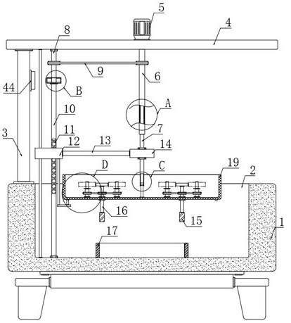
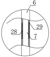
[0030] refer to Figure 1-6 , a synchronous oil immersion device for inner and outer rings of bearings for mechanical processing, comprising a housing 1, an oil immersion tank 2 is arranged on the upper end of the housing 1, a vertical plate 3 is fixedly connected to the upper end of the housing 1, and a horizontal plate 3 is installed on the upper end of the vertical plate 3 Plate 4, motor 5 is installed on the upper end of horizontal plate 4, the end of the output shaft of motor 5 runs through horizontal plate 4, and is fixedly connected with rotating tube 6, and the bottom of rotating tube 6 is provided with first rotating rod 7, and first rotating rod 7 The upper end of the upper end extends to the inside of the rotating tube 6, the second rotating rod 30 is arranged below the first rotating rod 7, and the rectangular sliding chamber 32 is arranged in the first rotating rod 7, and the upper end of the second rotating rod 30 extends to the rectangular sliding chamber 32, an...

Embodiment approach

[0031] As a kind of embodiment of the present invention, the lower end of horizontal plate 4 is provided with the moving mechanism that is used for moving screen frame 19, and moving mechanism comprises the second turning bar 10 that vertical rotation is connected in the bottom of oil immersion tank 2, and the second turning bar 10 A threaded layer 11 is provided on the top, and the threaded layer 11 is a threaded layer similar to a reciprocating screw rod to ensure that the unidirectional rotation of the second rotating rod 10 can drive the sliding block 12 to move up and down, and the threaded layer 11 of the second rotating rod 10 is partially threaded. Sliding block 12, horizontal plate 4 and the inner bottom of oil immersion tank 2 are vertically provided with guide rod, and guide rod runs through sliding block 12, and the right side of sliding block 12 is fixedly connected with connecting rod 13, and the right end of connecting rod 13 is fixedly connected with The connect...

Embodiment 2

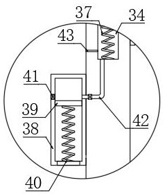
[0045] refer to Figure 7-9 The difference between this embodiment and Embodiment 1 is that two conductive blocks 33 are arranged on the left side inner wall of the oil immersion tank 2, the sliding block 12 is made of conductive material, and a vertical cavity 34 is arranged in the vertical plate 3, and the vertical The inner walls of both sides of the cavity 34 are provided with contact strips 36, and the vertical cavity 34 is provided with a conductive slider 35 for sliding up and down. The two contact strips 36 and the conductive slider 35 here together constitute a conductive assembly. , the conductive assembly is connected in series to the circuit where the electromagnet 44 is located, and the lower end of the conductive slider 35 is elastically connected to the inner bottom of the vertical cavity 34 through a restoring spring 37;

[0046] As an embodiment of the present invention, a trigger box 38 is provided on the left side wall of the riser 3, and a piston plate 39 f...


PUM


Abstract

The invention discloses a bearing inner and outer ring synchronous oil immersion device for machining. The device comprises a shell, wherein an oil immersion groove is formed in the upper end of the shell, a vertical plate is fixedly connected to the upper end of the shell, a transverse plate is installed at the upper end of the vertical plate, a motor is installed at the upper end of the transverse plate, the tail end of an output shaft of the motor penetrates through the transverse plate, the motor is fixedly connected with a rotating pipe, a first rotating rod is arranged below the rotating pipe, the upper end of the first rotating rod extends into the rotating pipe, a second rotating rod is arranged below the first rotating rod, and a rectangular sliding cavity is formed in the first rotating rod. According to the oil immersion device, on the basis that a good oil immersion effect is achieved, the operation process is simplified, the labor intensity of workers is reduced, and meanwhile in the oil throwing process, the good oil throwing effect is achieved through cooperation of a shaking structure and centrifugal force.

Description

technical field [0001] The invention relates to the field of mechanical parts processing, in particular to a synchronous oil immersion device for the inner and outer rings of a bearing used for mechanical processing. Background technique [0002] Bearing is an important part of mechanical equipment. It is usually used to support the rotating body on the machine for normal rotation. In order to prevent it from rusting, it needs to be oiled after its production is completed. But The existing oiling device cannot drive the inner ring and outer ring of the bearing to rotate synchronously, resulting in the inability to evenly oil the inner ring, outer ring and balls of the bearing; [0003] For this reason, the Chinese invention patent with the publication number "CN109647660B" discloses a synchronous oil immersion device for the inner and outer rings of bearings for mechanical processing, including a box, a motor, a first connecting gear and a transmission wheel, and the bottom ...

Claims


Application Information

Patent Timeline
IPC IPC(8): B05C3/10B05C11/10B05C13/02
CPCB05C3/10B05C11/1039B05C13/02
Inventor 龚毅
Owner 南通腾华新材料科技有限公司
Learn More