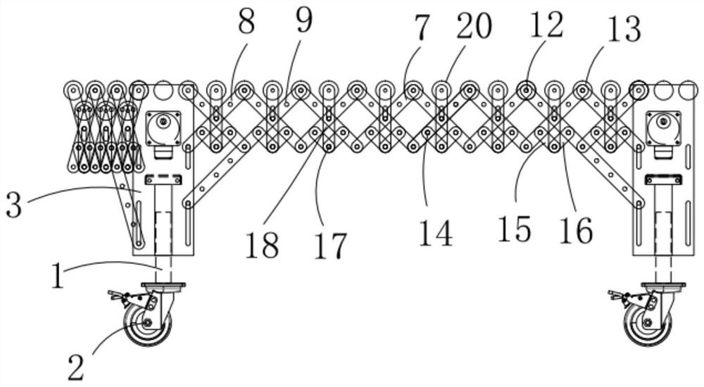
Electric telescopic conveyor capable of being stretched section by section and increasing distance between rollers
An electric telescopic and conveyor technology, which is applied in the field of telescopic machines, can solve the problems of large roller spacing, time-consuming and labor-intensive, unsuitable for conveying small objects, etc., and achieve the effect of facilitating transportation
- Summary
- Abstract
- Description
- Claims
- Application Information
AI Technical Summary
Problems solved by technology
Method used
Image

Examples
Embodiment Construction
[0027] The following descriptions are only preferred embodiments of the present invention, and are not intended to limit the scope of the present invention. For those skilled in the art, the present invention can have various modifications and changes; all within the spirit and principles of the present invention , any modifications, equivalent replacements, improvements, etc., should be included within the protection scope of the present invention.
[0028] In addition, the terms "vertical", "horizontal", "top", "bottom", "front", "rear", "upper", "lower", "inner" mentioned in the embodiments of the present invention The orientation or positional relationship indicated by , "outside" and so on is based on the attached figure 1 The orientation or positional relationship shown, or the orientation or positional relationship that the product is usually placed in use, is only for the convenience of describing the present invention and simplifying the description, rather than indic...
PUM
 Abstract
Description
Claims
Application Information