Speed reduction device, speed reduction system and speed reduction method

A deceleration device and deceleration system technology, applied in the field of pneumatic transmission, to achieve the effects of high control accuracy, avoidance of local turbulence and simple control

Active Publication Date: 2021-11-19
SICHUAN ORIENTER BIOLOGICAL TECH
View PDF7 Cites 1 Cited by
  • Summary
  • Abstract
  • Description
  • Claims
  • Application Information

AI Technical Summary

Problems solved by technology

[0004] In view of the existing problems in the background technology, the present invention provides a deceleration device, a deceleration system and a deceleration method. The samples in the pneumatic transmission system are decelerated through a non-pneumatic deceleration device with relatively simple construction, thereby avoiding the existing The construction of deceleration method is complicated, the cost is high, and the control requirements are high

Method used


Image

  • Speed reduction device, speed reduction system and speed reduction method
  • Speed reduction device, speed reduction system and speed reduction method
  • Speed reduction device, speed reduction system and speed reduction method

Examples


Embodiment

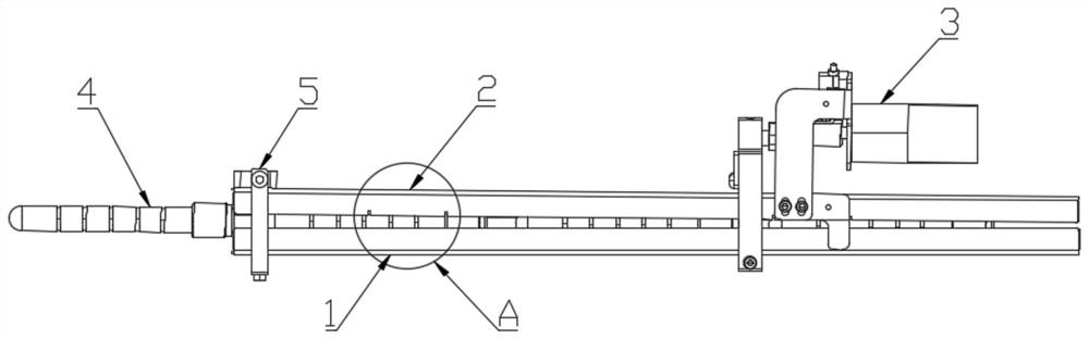
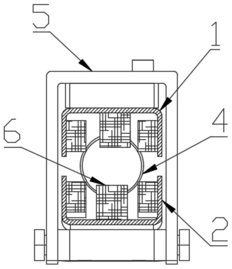
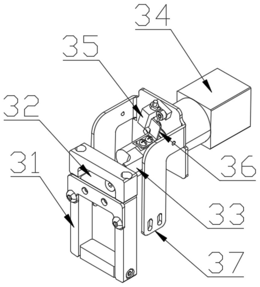
[0042] On the one hand, if figure 1 As shown, the present invention provides a deceleration device for decelerating samples in a pneumatic transmission system, including: a first assembly 1 having a through groove for radially limiting the sample tube 4 The second component 2, the second component 2 has elastic contact parts 6 arranged at intervals with the bottom of the through groove, and the elastic contact part 6 forms a sample channel with the through groove; the reducing device 3, The diameter reducing device 3 has a moving end 31, and the moving end 31 acts on the first component 1 and / or the second component 2 to make the diameter of the sample channel gradually decrease.

[0043] It can be understood that the basic function of the sample channel described in this embodiment is to transmit the sample tube 4, and it has the limiting function of the general transmission pipeline, that is, to prevent the sample tube 4 from flying out of the sample channel. , it can be se...


PUM


Abstract

The invention discloses a speed reduction device, a speed reduction system and a speed reduction method. The invention provides the non-pneumatic sample tube speed reduction device, the speed reduction system and the speed reduction method which are used in a pneumatic transmission system and do not need to modify a transmission pipeline. The speed reduction device comprises a first assembly, wherein the first assembly is provided with a through groove for radially limiting a sample tube; a second assembly provided with elastic contact parts, wherein the elastic contact parts and the groove bottom of the through groove are arranged at intervals, and the elastic contact parts and the through groove form a sample channel; and a diameter changing device provided with a moving end, wherein the moving end acts on the first assembly and/or the second assembly so that the drift diameter of the sample channel can have a gradually-decreasing change trend. The speed reduction device, the speed reduction system and the speed reduction method have the advantages of being convenient to implement, relatively simple in control precision requirement and the like.

Description

technical field [0001] The invention relates to the technical field of pneumatic transmission, in particular to a deceleration device, a deceleration system and a deceleration method. Background technique [0002] In the existing medical environment, many hospitals have successively installed pneumatic transmission systems for clinical samples due to the need to solve human efficiency problems, improve patient satisfaction, and connect with existing automation systems. The system is fast, efficient, and fast. The sample is transmitted to the designated place to achieve one-to-one, point-to-point reliable transmission. However, because it is driven by compressed air, the sample tube performs accelerated or high-speed motion in the transmission pipeline, so at the end of the transmission, if no measures are taken to stop the sample tube slowly, high-speed impact may occur, which may cause sample quality, Index parameters etc. are damaged. [0003] In view of the above proble...

Claims


Application Information

Patent Timeline
Patent Type & Authority Applications(China)
IPC IPC(8): B65G51/36B65G51/20
CPCB65G51/36B65G51/20
Inventor 杨龙贤徐建曹宝龙杨加兴
Owner SICHUAN ORIENTER BIOLOGICAL TECH
Why Eureka
Try Eureka