
Drainage structure of a house building

A technology for building drainage and housing, applied in roof drainage, building structure, construction, etc., can solve the problems of roof water accumulation, foreign objects easily sticking to the inner wall of the drainage hole, and the drainage hole is blocked, so as to achieve the effect of saving water resources.

Active Publication Date: 2022-08-02
浙江豪城建设有限公司
View PDF14 Cites 0 Cited by
  • Summary
  • Abstract
  • Description
  • Claims
  • Application Information

AI Technical Summary

Problems solved by technology

[0004] In view of the above-mentioned related technologies, the inventor believes that when the drain pipe is not in use, foreign matter will enter the drain pipe from above the drain hole, and when water passes through the drain pipe, the foreign matter will come into contact with the water, making the foreign matter easily stick to the drain hole On the inner wall, it is easy to block the drain hole, reduce the drainage efficiency of the drain pipe, and easily cause water to accumulate on the roof

Method used


Image

  • Drainage structure of a house building
  • Drainage structure of a house building
  • Drainage structure of a house building

Examples


Embodiment 1

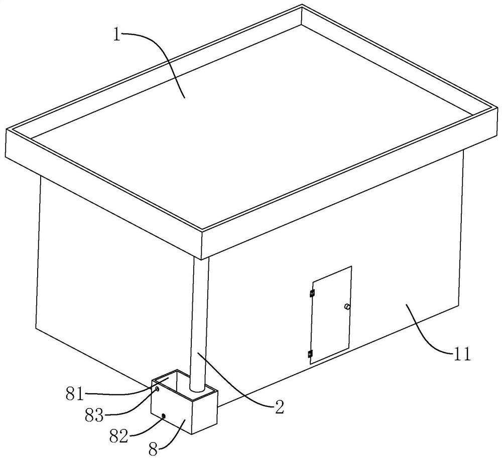
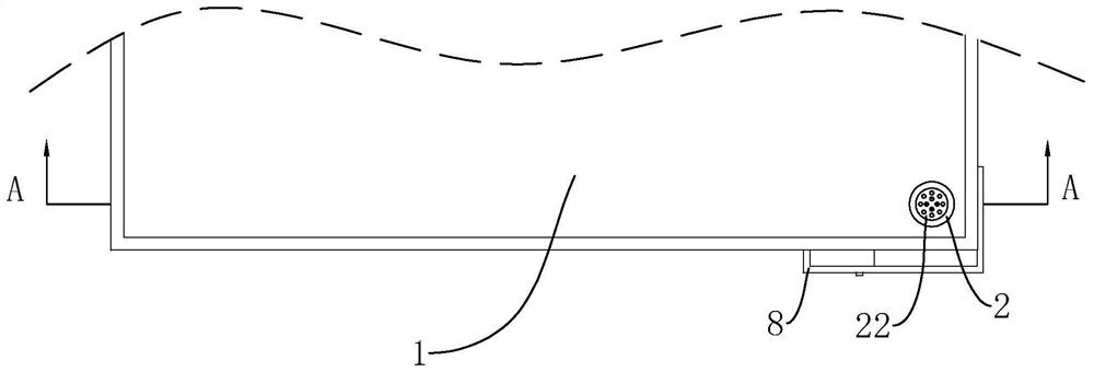
[0040] This embodiment discloses a house building drainage structure. refer to figure 1 and figure 2 , a house building drainage structure, including a wall 11 and a roof 1, the roof 1 is fixedly connected to the top of the wall 11.

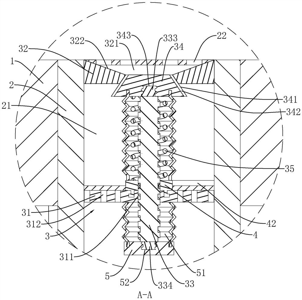
[0041] refer to figure 2 and image 3 The roof 1 is provided with a mounting hole, a drain pipe 2 is penetrated and fixedly connected in the mounting hole, and a drain hole 21 is provided on the upper end of the drain pipe 2 . The drain pipe 2 is provided with a blocking structure 3 , and the blocking structure 3 is located on the side of the drain hole 21 close to the upper opening. The blocking structure 3 includes a first fixing ring 31 , a second fixing ring 32 , a fixing rod 33 , a fixing disc 34 and a spring 35 . The outer wall of the first fixing ring 31 is fixedly connected with the inner wall of the drainage hole 21 , and the upper end of the first fixing ring 31 is provided with a first fixing hole 311 .

[0042] refer to imag...

Embodiment 2

[0056] refer to Image 6 The difference between this embodiment and Embodiment 1 is that the inner wall of the first fixing hole 311 is provided with a groove 43, the driving structure 7 includes a ball 73, the ball 73 is rotatably connected to the groove 43, and the ball 73 is slidably arranged in the groove 43. Inside the spiral groove 332 .

[0057] The implementation principle of the second embodiment is as follows: when the fixed rod 33 is limited by the limit block 6 and the first fixed hole 311 moves in the axial direction, the ball 73 is slidably arranged in the spiral groove 332, so that the movable ring 4 and the scraper 42 are moved. Rotate, so that the scraper 42 scrapes the dirt on the first fixing ring 31, and then the dirt is washed away by water.


PUM


Abstract

The present application relates to the technical field of house construction, and discloses a house building drainage structure, which comprises a roof, a mounting hole is opened on the roof, a drainage pipe is pierced and fixedly connected in the mounting hole, and a drainage hole is opened above the drainage pipe, A blocking structure is arranged in the drain pipe, and the blocking structure includes a first fixing ring and a second fixing ring fixedly connected with the inner wall of the drain hole, the first fixing ring is located below the second fixing ring, and the first fixing ring is provided with a first fixing ring. The fixing hole and the permeable hole, the second fixing ring is provided with a second fixing hole, the first fixing hole is provided with a fixing rod, the side of the fixing rod facing the second fixing ring is provided with a fixing plate, and the outer diameter of the fixing plate is larger than The inner diameter of the second fixing hole, the outer casing of the fixing rod is provided with a spring, and the two ends of the spring are respectively abutted with the first fixing ring and the fixing plate; when there is no force above the fixing plate, the fixing plate is in contact with the lower end surface of the second fixing ring , the application has the effect of preventing the clogging of the drain pipe.

Description

technical field [0001] The present application relates to the technical field of housing construction, and in particular, to a drainage structure for housing construction. Background technique [0002] Currently, a house is a building that houses people or stores things. [0003] In the related art, the house includes a roof, the roof is provided with through holes, the through holes are provided with drainage pipes, and the drainage pipes are provided with drainage holes. [0004] In view of the above-mentioned related art, the inventor believes that when the drain pipe is not in use, foreign matter will enter the drain pipe from above the drain hole. When water passes through the drain pipe, the foreign matter will contact with the water, so that the foreign matter is easy to stick to the drain hole. On the inner wall, it is easy to block the drainage hole, so that the drainage efficiency of the drainage pipe is reduced, and it is easy to cause the roof to accumulate wate...

Claims


Application Information

Patent Timeline
Patent Type & Authority Patents(China)
IPC IPC(8): E04D13/04
CPCE04D13/0409E04D2013/0413E04D2013/0495
Inventor 邱传映黄绍开周杰
Owner 浙江豪城建设有限公司
Learn More