Eureka AIR delivers breakthrough ideas for toughest innovation challenges, trusted by R&D personnel around the world.

Electric control cabinet vibration reduction device

A technology of shock absorption device and electric control cabinet, which is applied in spring/shock absorber, anti-vibration equipment, vibration suppression adjustment, etc. The effect of shock absorption, good shock absorption and strong applicability

Pending Publication Date: 2021-11-19
苏州华龙大金电加工机床有限公司
View PDF0 Cites 0 Cited by
  • Summary
  • Abstract
  • Description
  • Claims
  • Application Information

AI Technical Summary

Problems solved by technology

[0003] The deficiencies of the current damping devices for electric control cabinets are: the shock absorbing devices of electric control cabinets cannot be well applied to electric control cabinets of various specifications. It is not suitable for all kinds of electric control cabinets during installation, and the installation is more cumbersome. At the same time, when vibration occurs, the electric control cabinet cannot be stably limited. During the vibration, the electric control cabinet may shake or even tilt in various ways, which will affect the electric control cabinet. Normal operation of internal electronics

Method used


Image

  • Electric control cabinet vibration reduction device
  • Electric control cabinet vibration reduction device
  • Electric control cabinet vibration reduction device

Examples


Embodiment Construction

[0018] The following will clearly and completely describe the technical solutions in the embodiments of the present invention with reference to the accompanying drawings in the embodiments of the present invention. Obviously, the described embodiments are only some, not all, embodiments of the present invention. Based on the embodiments of the present invention, all other embodiments obtained by persons of ordinary skill in the art without making creative efforts belong to the protection scope of the present invention.

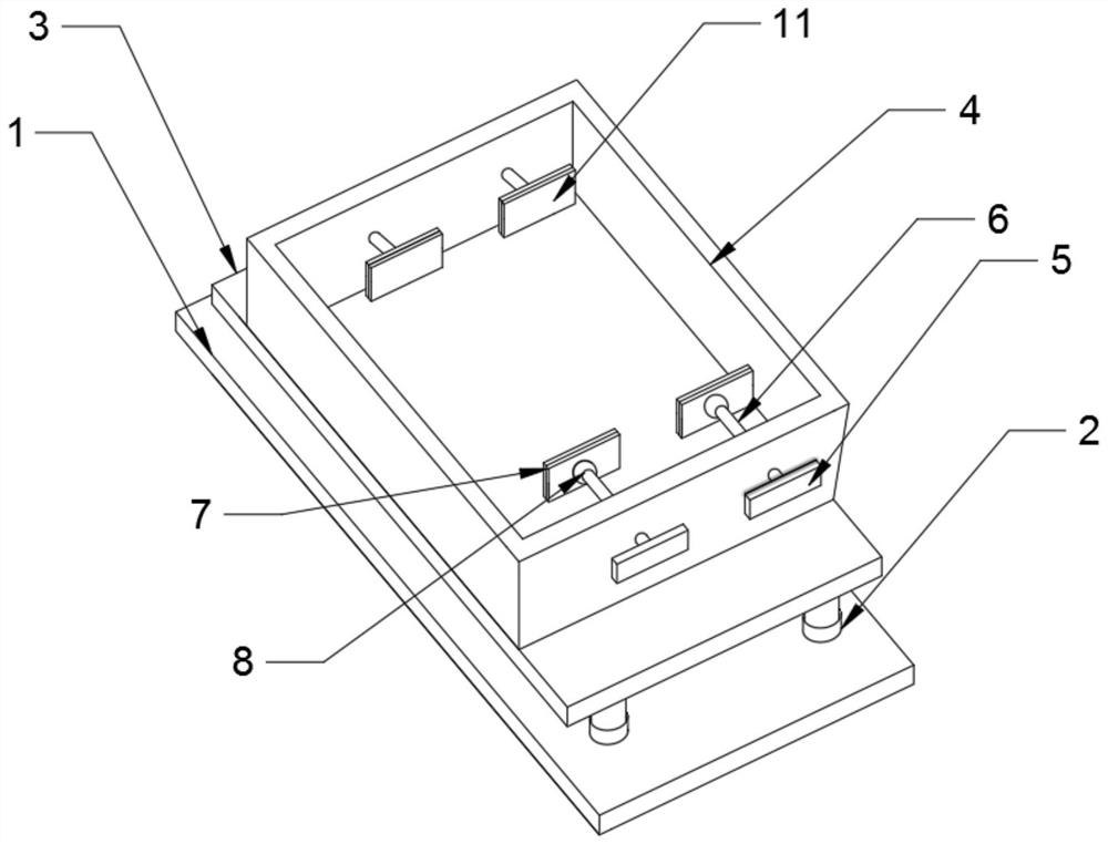
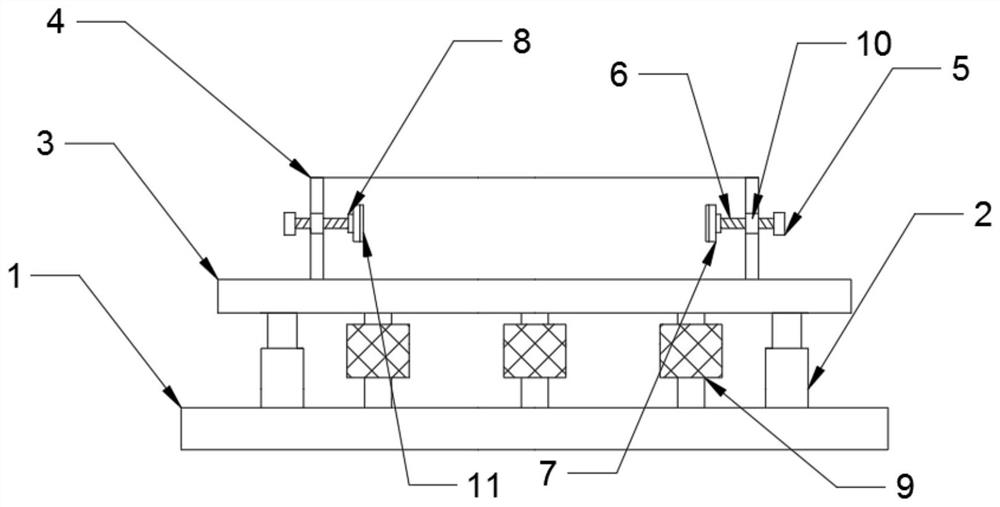
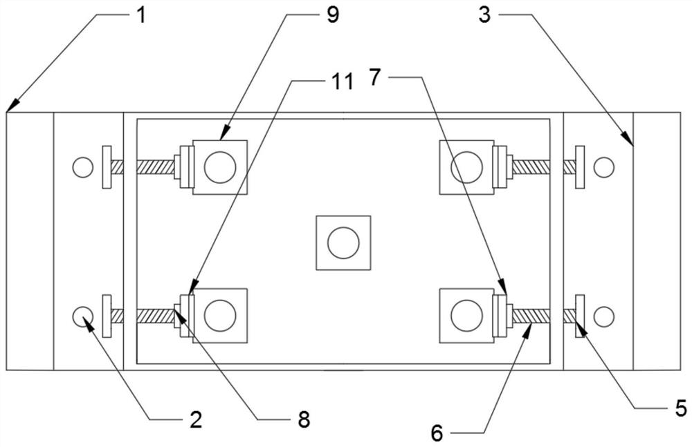
[0019] see Figure 1-4 , the present invention provides a technical solution: a damping device 9 for an electric control cabinet, including a base plate 1, a damping plate 3, a damping device 9, and a screw 6, and the four corners of the upper surface of the base plate 1 are fixedly installed with Telescopic rod 2, the upper end of described telescopic rod 2 at the four corners is all fixedly connected with shock absorbing plate 3, and the upper end surface of...


PUM


Abstract

The invention discloses an electric control cabinet vibration reduction device. The electric control cabinet vibration reduction device comprises a bottom plate, a vibration reduction plate, vibration reduction devices and screws, wherein telescopic rods are fixedly mounted at four corners of the upper surface of the bottom plate; the upper ends of the telescopic rods at the four corners are fixedly connected with the vibration reduction plate; a fixed frame is fixedly mounted on the upper end surface of the vibration reduction plate; the lower end surface of the vibration reduction plate is fixedly connected with the bottom plate through the vibration reduction devices; and each vibration reduction device comprises an upper supporting column, a lower supporting column, a limiting frame, a limiting block and a vibration reduction spring. According to the electric control cabinet vibration reduction device, rotating handles and clamping plates are arranged; different specifications of electric control cabinets can be more firmly limited and fixed through the four rotating handles on the left side and the right side; the clamping plates are used for preventing the electric control cabinets from shaking in a horizontal direction during vibration; the vibration reduction plate can be limited and fixed through the telescopic rods arranged between the bottom plate and the vibration reduction plate; and the electric control cabinet vibration reduction device has the advantages of stable structure, high applicability and good vibration reduction effect.

Description

technical field [0001] The invention relates to the technical field of motor equipment, in particular to a damping device for an electric control cabinet. Background technique [0002] Electric control cabinet is to assemble switchgear, measuring instrument, protective device and auxiliary equipment in closed or semiclosed metal cabinet or on screen width according to electrical wiring requirements, and its layout should meet the requirements of normal operation of power system, and is easy to overhaul and does not endanger people. A safe control cabinet for personal and surrounding equipment, through which the circuit adjustment and power system maintenance can be conveniently carried out; [0003] The deficiencies of the current damping device of the electric control cabinet are: the shock absorbing device of the electric control cabinet cannot be well applied to electric control cabinets of various specifications. It is not suitable for all kinds of electric control cabi...

Claims


Application Information

Patent Timeline
Patent Type & Authority Applications(China)
IPC IPC(8): F16F15/08H02B1/54
CPCF16F15/085H02B1/54
Inventor 张海潮
Owner 苏州华龙大金电加工机床有限公司
Why Eureka
Eureka Blog
Learn More