
Multidirectional synchronous telescopic and vertical lifting composite motion driving device

A compound motion and driving device technology, which is applied in the direction of transmission devices, belts/chains/gears, mechanical equipment, etc., can solve the problems of inability to achieve light weight, bloated mechanism, low transmission efficiency, etc., and achieve large-scale synchronous telescopic movement, The effect of improving the smoothness of transmission and reducing the quality of transmission

Active Publication Date: 2021-11-19
广东空天科技研究院 +1
View PDF3 Cites 2 Cited by
  • Summary
  • Abstract
  • Description
  • Claims
  • Application Information

AI Technical Summary

Problems solved by technology

[0004] At present, various electric chucks and docking mechanisms can convert motor drive into multi-directional linear motion. However, these electric chucks and docking mechanisms cannot realize multi-directional synchronous expansion and vertical lifting compound motion, nor can they establish synchronous expansion and vertical lifting. Due to the gear transmission of various chucks, the mechanism is bloated, the weight is large, the transmission efficiency is low, and the range of motion is limited, so it is impossible to achieve light weight, high-efficiency transmission, and large-scale motion.

Method used


Image

  • Multidirectional synchronous telescopic and vertical lifting composite motion driving device
  • Multidirectional synchronous telescopic and vertical lifting composite motion driving device
  • Multidirectional synchronous telescopic and vertical lifting composite motion driving device

Examples


Embodiment Construction

[0034] Design principle of the present invention

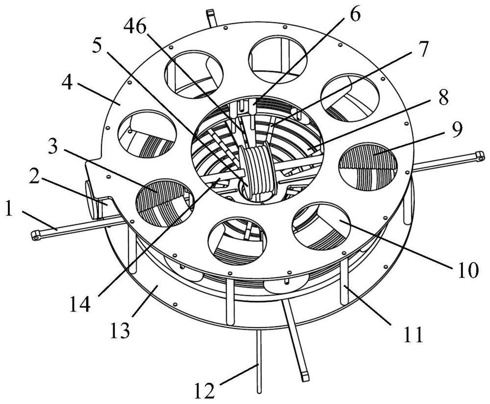
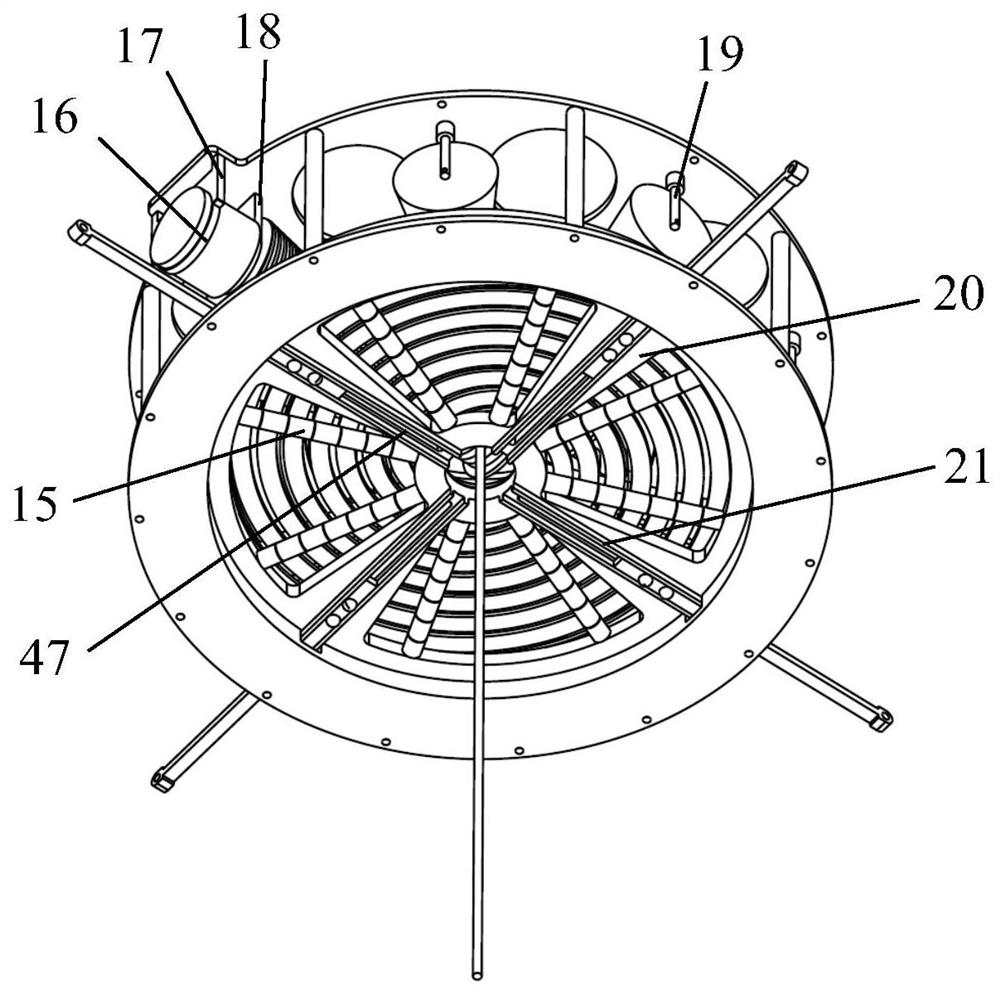
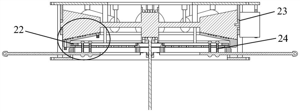
[0035] 1. The design principle of the compound motion drive device. The motor drives the cone → the cone drives the hoist to do the lifting movement → at the same time the cone drives the upper plate 44 of the spiral plate to rotate → the upper plate 44 of the spiral plate drives the lower plate 43 of the spiral plate to rotate through the rope → the lower plate 43 of the spiral plate rotates to drive the pins in the lower plate along the The Archimedes spiral groove performs spiral rotation → at the same time, the pin penetrates the lower plate 43 of the spiral plate and enters the linear groove under the plate, and drives the telescopic rod in the linear groove to perform linear motion while doing the spiral motion → the pin moves along the direction of Archimedes Every time the direction of the spiral groove increases one turn towards the direction of the large radius, the telescopic rod in the linear groove will stretch ou...


PUM


Abstract

The invention discloses a multidirectional synchronous telescopic and vertical lifting composite motion driving device. The composite motion driving device is divided into an upper layer and a lower layer, wherein the upper layer is provided with a conical rope spiral groove rope transmission mechanism and a lifting mechanism, and the lower layer is provided with an Archimedes spiral groove multidirectional synchronous telescopic mechanism. The composite motion driving device is characterized in that rotary motion of a motor is converted into spiral motion and lifting motion; the spiral motion of the upper layer is converted into multidirectional synchronous telescopic motion at the same time at the lower layer; and the upper layer comprises an upper spiral disc and a mechanism above the upper spiral disc, and the lower layer mechanism comprises a lower spiral disc and a mechanism below the lower spiral disc. The composite motion driving device solves the problems that in the prior art, an electric chuck and a butt joint mechanism cannot achieve multidirectional synchronous telescopic and vertical lifting composite motion, an accurate transmission proportional relation of synchronous telescopic and vertical lifting cannot be established, gear transmission is adopted for various chucks, the mechanism is bloated, the weight is great, the transmission efficiency is low, the motion range is limited, and light weight cannot be achieved.

Description

technical field [0001] The invention belongs to the technical field of compound motion driving devices, and in particular relates to a multi-directional synchronous telescopic and vertical lifting compound motion driving device. Background technique [0002] Simple motion can only realize one motor to drive one action, and compound motion can realize one motor to drive multiple actions to move simultaneously, thus realizing multi-mechanism synchronous motion. [0003] A chuck is a mechanical device used to clamp a workpiece on a machine tool. A machine tool accessory that clamps and positions workpieces by using the radial movement of movable jaws evenly distributed on the chuck body. The chuck is generally composed of three parts: the chuck body, the movable jaw and the jaw driving mechanism. The minimum diameter of the chuck body is 65mm, and the maximum can reach 1500mm. There is a through hole in the center to pass the workpiece or bar; the back has a cylindrical or sh...

Claims


Application Information

Patent Timeline
IPC IPC(8): F16H37/12B23B31/02B23B31/24
CPCF16H37/124B23B31/02B23B31/24
Inventor 王福德胡灯亮申亮李腾李文皓
Owner 广东空天科技研究院
Learn More