Magnetic declination measuring method based on high-precision electronic compass

An electronic compass and measurement method technology, applied in directions such as compass, measurement device, surveying, mapping and navigation, can solve the problems that the measurement method cannot meet people's requirements, cannot measure the magnetic declination angle of the airport well, and achieve reliable data support. , Improve the effect of application scenarios

Pending Publication Date: 2021-11-19
广东海纬地恒空间信息技术有限公司
View PDF0 Cites 0 Cited by
  • Summary
  • Abstract
  • Description
  • Claims
  • Application Information

AI Technical Summary

Problems solved by technology

[0005] Aiming at the deficiencies of the prior art, the present invention provides a magnetic declination measurement method based on a high-precision electronic compass, which solves the problem that the conventional theodolite measurement method is difficult to meet people's requirements and cannot measure the magnetic declination of the airport well. angle problem

Method used


Image

  • Magnetic declination measuring method based on high-precision electronic compass
  • Magnetic declination measuring method based on high-precision electronic compass
  • Magnetic declination measuring method based on high-precision electronic compass

Examples


Embodiment 1

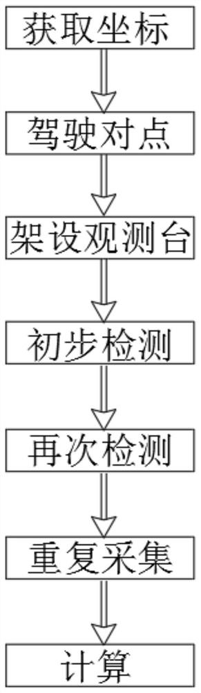
[0034] refer to Figure 1-4 , a method for measuring magnetic declination based on a high-precision electronic compass, comprising the following steps:

[0035] S1: Obtain the coordinates. In the area of ​​the airport runway, select an open field with a good non-magnetic environment. At least 20 meters parallel to the direction of the airport runway, use non-magnetic materials to lay out positioning piles A and B with an interval of 400 meters. Use a total station or GPS observes the positioning pile, and obtains the local control coordinate results and the latitude and longitude coordinates of WGS84;

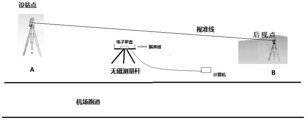
[0036] S2: Set up the point alignment, erect the conventional theodolite on the positioning pile A to complete the downward point alignment, and at the same time erect the backsight target on another positioning pile B to complete the downward point alignment, and then turn the theodolite A to point to the backsight target B, fix the direction of the theodolite collimation axi...

Embodiment 2

[0044] refer to Figure 1-4 , a method for measuring magnetic declination based on a high-precision electronic compass, comprising the following steps:

[0045] S1: Obtain the coordinates. In the area of ​​the airport runway, select an open field with a good non-magnetic environment. At least 20 meters parallel to the direction of the airport runway, use non-magnetic materials to lay out positioning piles A and B with an interval of 400 meters. Use a total station or GPS observes the positioning pile, and obtains the local control coordinate results and the latitude and longitude coordinates of WGS84;

[0046] S2: Set up the point alignment, erect the conventional theodolite on the positioning pile A to complete the downward point alignment, and at the same time erect the rear-sight target on another positioning pile B to complete the downward alignment, and then turn the theodolite A to point to the rear-sight target B, fix the direction of the theodolite collimation axis te...


PUM


Abstract

The invention relates to the technical field of magnetic declination measurement, and discloses a magnetic declination measuring method based on a high-precision electronic compass. The method comprises the steps of S1 acquiring coordinates, selecting an open field with a good non-magnetic environment in an airport runway area, arranging positioning piles A and B, observing the positioning piles by using a total station or a GPS, and acquiring a local control coordinate result and latitude and longitude coordinates of the WGS84; S2 carrying out point alignment, specifically, carrying out point alignment on a conventional theodolite frame and a rearview target, and then carrying out fixing; and S3 erecting an observation platform. According to the method, the magnetic declination meeting the standard requirement can be calculated through observation of a full-circle observation method of a non-magnetic high-precision electronic compass measuring rod, magnetic declination measurement without a non-magnetic theodolite and a high-precision magnetometer is achieved, the application scene can be greatly improved, and reliable data support is provided for construction, operation and maintenance and navigation of an airport.

Description

technical field [0001] The invention relates to the technical field of magnetic declination measurement, in particular to a magnetic declination measurement method based on a high-precision electronic compass. Background technique [0002] In recent years, with the rapid development of my country's economy, airports are an effective means of solving traffic and logistics transportation. Airport construction in various places is in the ascendant. By 2020, the total number of general-purpose airports in my country will exceed 340, and the total number of airports will soon exceed 500 in the next five years. [0003] Magnetic declination is an important measurement data in airport construction. The current airport specification requires the measurement accuracy of magnetic declination to be better than 0.1°. However, the current textbooks and relevant measurement specifications do not give relevant solutions. Based on the current practice, there are more The methods are 1. Non-...

Claims


Application Information

Patent Timeline
IPC IPC(8): G01C17/32
CPCG01C17/32
Inventor 潘清存谢劲松苏鹏
Owner 广东海纬地恒空间信息技术有限公司
Why Eureka
Try Eureka