Welding gun mounting device

An installation device and welding torch technology, applied in auxiliary devices, welding equipment, auxiliary welding equipment and other directions, can solve the problem of difficulty in adjusting the position of the welding torch, and achieve the effect of improving the application scene, convenient operation and high adjustment accuracy

Pending Publication Date: 2022-01-11
LANZHOU UNIVERSITY OF TECHNOLOGY
View PDF0 Cites 0 Cited by
  • Summary
  • Abstract
  • Description
  • Claims
  • Application Information

AI Technical Summary

Problems solved by technology

[0004] The purpose of the present invention is to solve the problem of difficulty in adjusting the position of the welding torch of the automatic welding equipment in the rectangular coordinate system

Method used


Image

  • Welding gun mounting device
  • Welding gun mounting device
  • Welding gun mounting device

Examples


Embodiment Construction

[0058] The implementation of the present invention will be illustrated by specific specific examples below, and those skilled in the art can easily understand other advantages and effects of the present invention from the content disclosed in this specification. Although the description of the present invention will be presented in conjunction with a preferred embodiment, it does not mean that the features of the invention are limited to this embodiment. On the contrary, the purpose of introducing the invention in conjunction with the embodiments is to cover other options or modifications that may be extended based on the claims of the present invention. The following description contains numerous specific details in order to provide a thorough understanding of the present invention. The invention may also be practiced without these details. Also, some specific details will be omitted from the description in order to avoid obscuring or obscuring the gist of the present invent...


PUM


Abstract

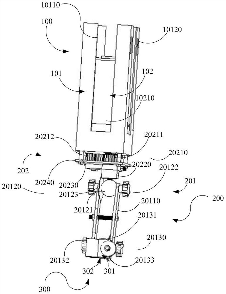
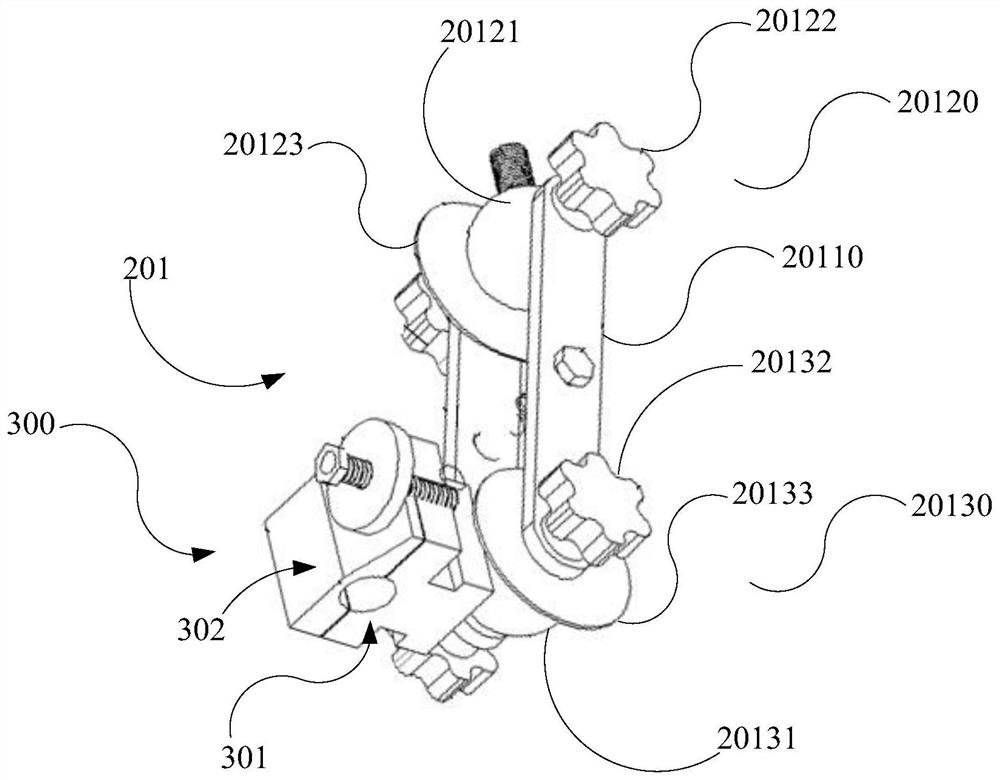
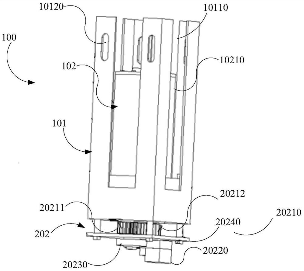
The invention discloses a welding gun mounting device which comprises a mounting component, a rotating component and a welding gun clamping component. One end of the rotating component is rotatably connected with the mounting component, and the other end of the rotating component is detachably connected with the welding gun clamping component. The mounting component comprises a mounting arm and a driving assembly, the driving assembly is mounted on a fixed seat arranged on the mounting arm, the rotating component comprises a connecting assembly and a rotating arm, the connecting assembly is rotatably connected with the end, close to the driving assembly, of the rotating arm in a lockable manner, and the connecting assembly is further in transmission connection with the driving assembly; and the welding gun clamping component is rotationally connected to the end, away from the driving assembly, of the rotating arm in a lockable mode. The welding gun mounting device is specially used for rectangular coordinate automatic welding equipment, adjustment is completed through driving of the driving assembly, then the position, relative to the mounting arm, of the rotating arm and the position, relative to the rotating arm, of the welding gun clamping component are manually adjusted, the position of a welding gun can be adjusted in a narrow space, and therefore the application scene of the rectangular coordinate automatic welding equipment is expanded.

Description

technical field [0001] The invention relates to the field of welding automation, in particular to a welding torch installation device. Background technique [0002] The mechanization and automation of the welding process is an important development of modern welding technology. With the development of science and technology, robot technology is becoming more and more mature, and more and more automatic welding equipment has replaced manual welding in the field of welding. Automatic welding machines have been widely used in plastics, automobile manufacturing, metal processing, machining and manufacturing, aerospace and other fields. After the application of the automatic welding machine, the appearance and internal quality of the welded parts are greatly improved, and the stability of the quality is guaranteed, the labor intensity is reduced, the working environment is improved, the manual welding skill requirements and production costs are reduced, and the production efficie...

Claims


Application Information

Patent Timeline
IPC IPC(8): B23K37/02
CPCB23K37/02
Inventor 张鹏贤颜申周文博雷飚张瑾李锦龙杨鑫
Owner LANZHOU UNIVERSITY OF TECHNOLOGY
Why Eureka
Try Eureka