
Airborne SAR motion compensation method based on inertial navigation system parameters

An inertial navigation system and motion compensation technology, which is used in radio wave measurement systems, navigation, surveying and navigation, etc., to solve problems such as the flight trajectory of the carrier deviates from the ideal position, the image quality is reduced, and the image cannot be imaged.

Pending Publication Date: 2021-11-19
XIDIAN UNIV
View PDF4 Cites 2 Cited by
  • Summary
  • Abstract
  • Description
  • Claims
  • Application Information

AI Technical Summary

Problems solved by technology

[0004] The imaging algorithm is based on the model of the carrier aircraft flying straight along the ideal heading, but in reality, the airborne SAR flight is easily affected by the airflow, causing the flight trajectory of the carrier aircraft to deviate from the ideal position, which will lead to Image quality degrades or even fails to image

Method used


Image

  • Airborne SAR motion compensation method based on inertial navigation system parameters
  • Airborne SAR motion compensation method based on inertial navigation system parameters
  • Airborne SAR motion compensation method based on inertial navigation system parameters

Examples

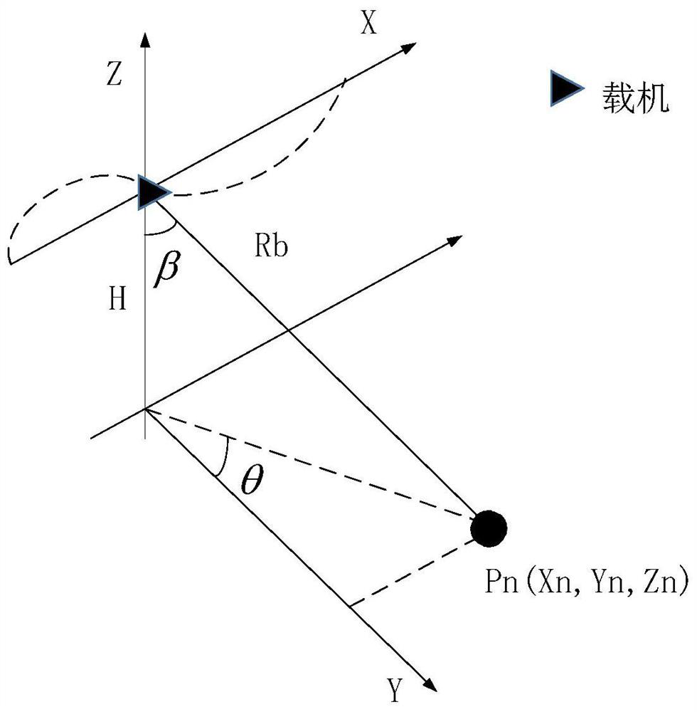

Embodiment Construction

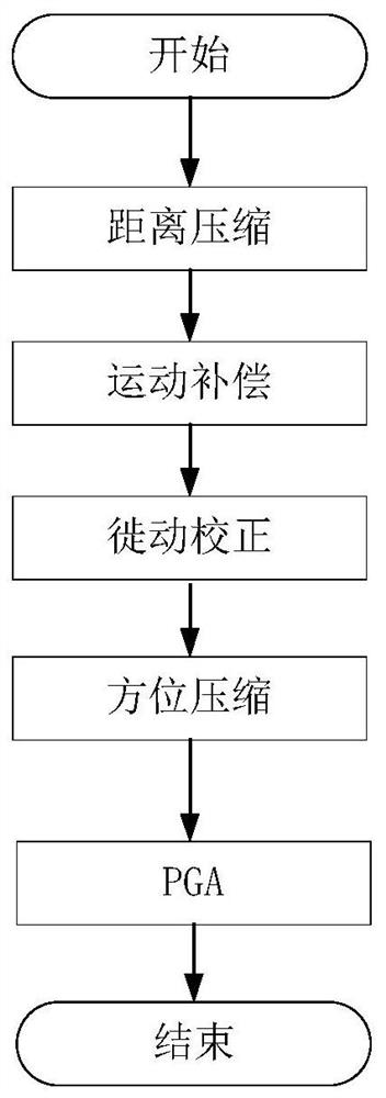
[0025] The turbulence of the carrier aircraft affected by the airflow is mainly manifested in two aspects: one is the position change of the carrier aircraft, and the other is the attitude change of the carrier aircraft. Both are three-dimensional. The present invention studies the influence of the motion error on imaging due to the position change of the carrier aircraft. The influence of the attitude change of the carrier aircraft is offset by the antenna stabilization platform, which is not considered.

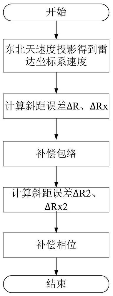
[0026] The present invention constructs the instantaneous slant distance equation between the carrier aircraft and the target by establishing the motion error model of the carrier aircraft, and obtains the velocity components of the carrier aircraft along the three directions of X axis, Y axis and Z axis and the instantaneous slant distance error after approximating the equation Finally, the envelope of the echo signal after the pulse pressure is compensated in the distance ...


PUM


Abstract

The invention discloses a motion compensation method based on inertial navigation system parameters, which comprises the following steps of establishing a radar coordinate system and a motion error model, and collecting the inertial navigation system parameters in real time, establishing an instantaneous slant distance equation of the airborne SAR to obtain an instantaneous slant distance error formula, and separating an influence value deltaR of position errors of the aerial carrier along the Y axis and the Z axis on the instantaneous slant distance error and an influence value deltaRx of position errors of the aerial carrier along the X axis direction on the instantaneous slant distance error, then calculating the actual course angle and the actual course speed of the aerial carrier by using the parameters of the inertial navigation system, projecting the speed of the actual course of the aerial carrier to a radar coordinate system to obtain the actual positions of the aerial carrier along the X-axis, Y-axis and Z-axis directions, sequentially calculating deltaR, deltaRx and an envelope compensation function H1, and performing envelope compensation on the echo signal, and finally, calculating a phase compensation function H2, and performing phase compensation on the echo signal, thereby completing motion compensation of the echo signal.

Description

technical field [0001] The invention belongs to the field of flight airborne radar imaging, and relates to a motion compensation method based on inertial navigation system parameters, specifically an accelerometer and gyroscope based on an inertial measurement unit (IMU) or an inertial navigation system (INS). The method of motion compensation based on the parameter data can be applied to compensate the position error caused by the unsteady motion of the airborne SAR platform, and obtain high-quality SAR images. Background technique [0002] Synthetic Aperture Radar (SAR) has the advantages of all-time, all-weather, long-distance, high-resolution and wide swath, and has been widely used in various fields. For example, in terms of military reconnaissance, high-resolution images obtained by synthetic aperture radar are an important means to understand the battlefield situation and obtain enemy intelligence; in terms of microwave remote sensing, images obtained by synthetic ape...

Claims


Application Information

Patent Timeline
Patent Type & Authority Applications(China)
IPC IPC(8): G01C21/16G01S13/86G01S13/90
CPCG01C21/165G01S13/86G01S13/90
Inventor 苏涛王瑞秋孙旗梁远
Owner XIDIAN UNIV
Learn More