Coil insulating layer detection device applied to motor coil

A detection device and coil insulation technology, which is applied in the direction of measuring devices, measuring device casings, electrical measuring instrument parts, etc., can solve the problems of low detection accuracy, waste of time, poor coil fixing effect, etc., to increase the detection effect, detect High precision and good fixing effect

Active Publication Date: 2021-11-19
常州豪基电器有限公司
View PDF6 Cites 0 Cited by
  • Summary
  • Abstract
  • Description
  • Claims
  • Application Information

AI Technical Summary

Problems solved by technology

[0002] Motor coils include stator coils and rotor coils. Motor coils are prone to damage to the insulation layer after long-term use. After the insulation layer is damaged, the coil will generate heat and leak current when it is energized, which poses a great safety hazard.
[0003] When the existing motor coil insulation layer detection device performs insulation detection on the stator coil or the rotor coil, because the diameters of the rotor coil and the stator coil are different, different coil fixing devices need to be replaced, and the fixing effect on the coil is poor, which is wasteful. Time is not conducive to the insulation layer damage detection of the coil to be detected, and the existing motor coil insulation layer detection device judges the damage of the insulation layer according to the leakage current, the detection accuracy is low, and in the detection process, the detection coil cannot be detected. Marking the damaged position of the insulating layer is not conducive to the later repair of the coil to be detected, and reduces the detection effect of the detection device

Method used


Image

  • Coil insulating layer detection device applied to motor coil
  • Coil insulating layer detection device applied to motor coil
  • Coil insulating layer detection device applied to motor coil

Examples


Embodiment Construction

[0028] The following will clearly and completely describe the technical solutions in the embodiments of the present invention with reference to the accompanying drawings in the embodiments of the present invention. Obviously, the described embodiments are only some, not all, embodiments of the present invention. Based on the embodiments of the present invention, all other embodiments obtained by persons of ordinary skill in the art without making creative efforts belong to the protection scope of the present invention.

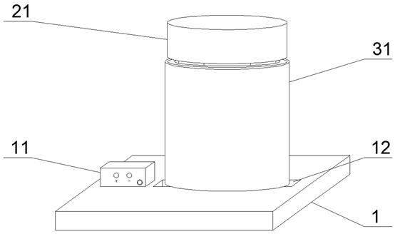
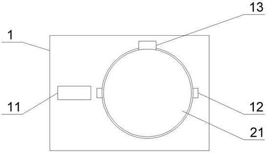
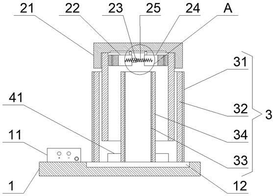
[0029] see Figure 1-7 , the present invention provides a technical solution: including a detection table 1 and a fixing device 2, the fixing device 2 is installed above the detection table 1 through a telescopic rotating rod 13, and the fixing device 2 includes an end cover 21, a first fixing member 22, an automatic telescopic rod 23, The second fixing part 24, the spring 25 and the push-in assembly 26, the end cover 21 is used to install the first fixing par...


PUM


Abstract

The invention discloses a coil insulating layer detection device applied to a motor coil, and belongs to the technical field of motor manufacturing and detection. The device comprises a detection table and a fixing device, the fixing device is located above the detection table, the fixing device comprises an end cover, a first fixing piece, an automatic telescopic rod, a second fixing piece, a spring and an inward pushing assembly, and the first fixing piece and the second fixing piece are slidably installed in an inner cavity of the end cover; the two ends of the first fixing piece and the second fixing piece are connected through automatic telescopic rods, a spring is fixedly installed between the first fixing piece and the second fixing piece, inner pushing assemblies are fixedly installed on the inner sides of the first fixing piece and the second fixing piece, and the first fixing piece is used for being matched with the second fixing piece to support and fix a to-be-detected coil; and the automatic telescopic rod is used for adjusting the distance between the first fixing piece and the second fixing piece, so that the rotor coils with different diameters can be effectively fixed.

Description

technical field [0001] The invention relates to the technical field of motor manufacturing detection, in particular to a coil insulation layer detection device applied to motor coils. Background technique [0002] Motor coils include stator coils and rotor coils. Motor coils are prone to damage to the insulation layer after long-term use. After the insulation layer is damaged, the coil will generate heat and leak current when it is energized, which poses a great safety hazard. [0003] When the existing motor coil insulation layer detection device performs insulation detection on the stator coil or the rotor coil, because the diameters of the rotor coil and the stator coil are different, different coil fixing devices need to be replaced, and the fixing effect on the coil is poor, which is wasteful. Time is not conducive to the insulation layer damage detection of the coil to be detected, and the existing motor coil insulation layer detection device judges the damage of the i...

Claims


Application Information

Patent Timeline
Patent Type & Authority Applications(China)
IPC IPC(8): G01R31/52G01R1/04G01N25/72G01K11/12
CPCG01R31/52G01R1/0408G01N25/72G01K11/12
Inventor 万荣山万荣松
Owner 常州豪基电器有限公司
Why Eureka
Try Eureka