A laser ranging accuracy calibration method and system

A technology of laser distance measurement and calibration method, which is applied in the direction of radio wave measurement systems, measuring instruments, measuring devices, etc., can solve the problems of complex adjustment and test steps, and achieve the effect of ensuring accuracy, ensuring calibration accuracy, and simple operation

Active Publication Date: 2022-07-22
北京波谱华光科技有限公司
View PDF0 Cites 0 Cited by
  • Summary
  • Abstract
  • Description
  • Claims
  • Application Information

AI Technical Summary

Problems solved by technology

[0004] The pulsed laser ranging high-precision calibration system based on the total station proposed by the existing scheme uses the total station and the target to perform laser ranging calibration on the laser rangefinder, in which the station instrument, the target and the laser ranging The laser rangefinders are distributed in a triangle. During the measurement process, the angles of the laser rangefinder and the total station need to be adjusted repeatedly to ensure that the cross center of the sight mirror of the laser rangefinder coincides with the cross center of the target. The total station needs to measure the emission of the laser rangefinder separately The cross center between the window and the target, so a distance point needs to be adjusted three times to measure the angle, and the adjustment test steps are more complicated

Method used


Image

  • A laser ranging accuracy calibration method and system
  • A laser ranging accuracy calibration method and system

Examples


Embodiment Construction

[0047] The principles and features of the present invention will be described below with reference to the accompanying drawings. The examples are only used to explain the present invention, but not to limit the scope of the present invention.

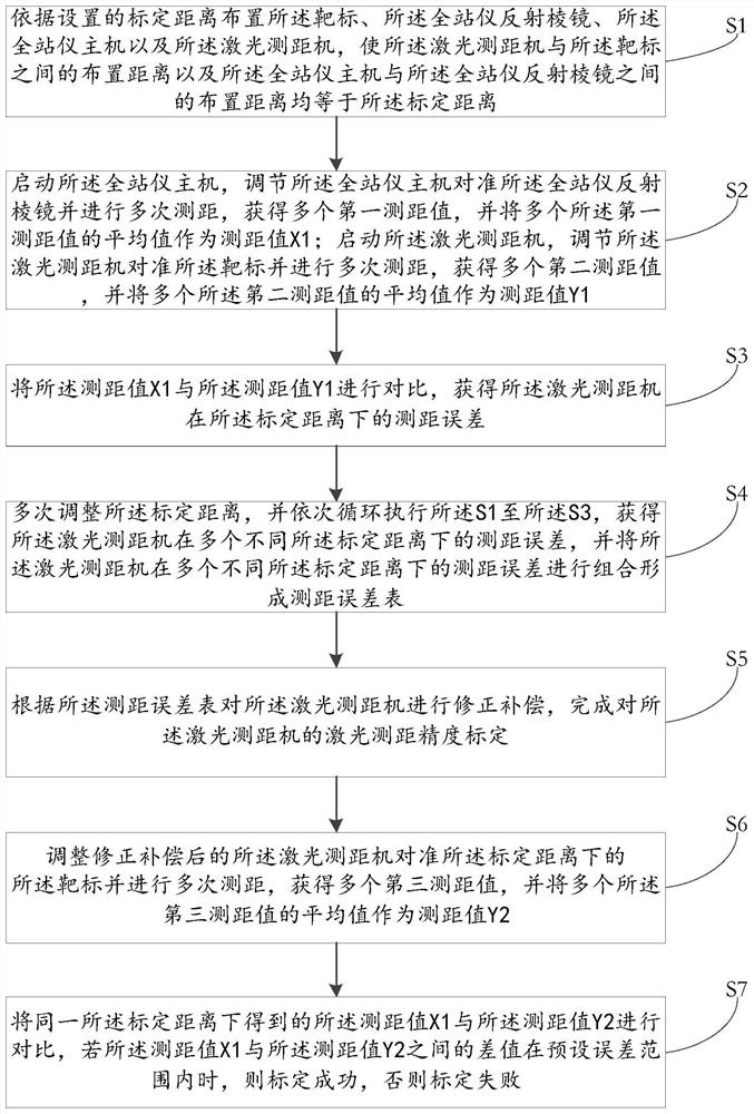
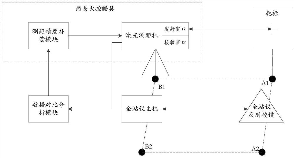
[0048] like figure 1 As shown, a method for calibrating the accuracy of laser ranging, using a target, a total station reflecting prism and a total station host to calibrate the laser ranging accuracy of a laser ranging machine, including the following steps:

[0049] S1, the target, the total station reflecting prism, the total station host and the laser rangefinder are arranged according to the set calibration distance, so that the distance between the laser rangefinder and the target is arranged And the arrangement distance between the total station host and the total station reflecting prism is equal to the calibration distance.

[0050] In this specific embodiment:

[0051] The reflecting prism of the total station is a triangula...


PUM


Abstract

The invention relates to a method and system for calibrating the accuracy of laser ranging. The method includes the following steps: arranging a target, a total station reflecting prism, a total station host and a laser ranging machine according to the calibrated distance, so that the laser ranging machine and the target are connected to each other. The arrangement distance between the total station host and the total station reflecting prism is equal to the calibration distance; the total station host aligns the total station reflecting prism and performs ranging, and outputs the ranging value X1; laser ranging The machine aligns the target and measures the distance, and outputs the distance measurement value Y1; compares the distance measurement value X1 with the distance measurement value Y1, obtains the distance measurement error of the laser rangefinder at the calibrated distance, and forms a distance measurement error table; The ranging error table corrects and compensates the laser ranging machine. The invention uses a station to calibrate the laser ranging machine, and the ranging accuracy is accurate; in the process of calibration, it is only necessary to ensure that the cross center of the sighting scope of the laser ranging machine and the center of the target cross are coincident, so the adjustment operation is simple.

Description

technical field [0001] The invention relates to the field of laser ranging correction, in particular to a laser ranging precision calibration method and system. Background technique [0002] The pulsed laser ranging machine emits a beam or a series of short-lived pulsed laser beams to the target during operation, and the photoelectric element receives the laser beam reflected by the target. distance to the target. The laser rangefinder is light in weight, small in size, simple in operation, fast and accurate, and its error is only one fifth to several hundredths of other optical rangefinders. With the development of science and technology, the requirements for laser ranging accuracy are getting higher and higher in some applications, especially the use of laser ranging in weapons. [0003] The pulsed laser ranging machine has the characteristics of high ranging repeatability but low absolute ranging accuracy. And according to the experimental results, the difference betwe...

Claims


Application Information

Patent Timeline
Patent Type & Authority Patents(China)
IPC IPC(8): G01S7/497G01S17/08G01C15/00
CPCG01S7/497G01S17/08G01C15/00
Inventor 祁海军兰世龙赵金博王卓
Owner 北京波谱华光科技有限公司
Why Eureka
Try Eureka