Display device and gate enabling method thereof

A display device, the ultimate technology, applied in static indicators, instruments, etc., can solve the problem that the display pixels cannot reach the target voltage, and achieve the effect of avoiding waste of electricity, small hardware area, and low manufacturing cost

Active Publication Date: 2021-11-19
APLUS SEMICON TECH CO LTD
View PDF10 Cites 0 Cited by
  • Summary
  • Abstract
  • Description
  • Claims
  • Application Information

AI Technical Summary

Problems solved by technology

[0004] The technical problem to be solved by the present invention is: in order to solve the technical problem in the prior art that the dis

Method used


Image

  • Display device and gate enabling method thereof
  • Display device and gate enabling method thereof
  • Display device and gate enabling method thereof

Examples


Embodiment Construction

[0048] The present invention is described in further detail now in conjunction with accompanying drawing. These drawings are all simplified schematic diagrams, which only illustrate the basic structure of the present invention in a schematic manner, so they only show the configurations related to the present invention.

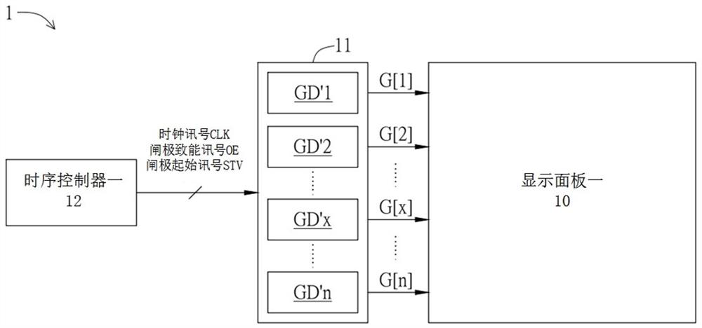
[0049] Such as figure 1 As shown, the display device 1 includes a display panel 10 , a gate driver 11 and a timing controller 12 . Structurally, the gate driver 11 is coupled between the timing controller 12 and the display panel 10, and is used to generate a clock signal CLK, a gate enable signal OE and a gate according to the timing controller 12. The start signal STV generates a plurality of gate output signals G[1] . . . G[x] . . . G[n] to the display panel 1 10 . The display panel 10 includes n gate channels, and the gate driver 11 includes a plurality of gate driving units GD'1...GD'x...GD'n, which are used to respectively output a plurality of gate ou...


PUM


Abstract

The invention discloses a display device. The display device comprises a display panel, a time schedule controller, a gate enabling frequency division controller and a gate driver, and the time schedule controller is used for generating a clock signal, a gate starting signal and a gate enabling signal. The gate enabling frequency division controller is coupled to the time schedule controller and is used for generating a plurality of frequency division gate enabling signals according to the clock signal, the gate starting signal and the gate enabling signal. The gate driver is coupled to the time schedule controller, the gate enabling frequency division controller and the display panel, and is used for generating a plurality of gate output signals to the display panel according to the clock signal, the gate starting signal and the plurality of frequency division gate enabling signals. According to the invention, the display device does not have a section of redundant pre-charging and discharging, so that waste of electricity can be avoided.

Description

technical field [0001] The present invention relates to the technical field of display panels, in particular to a display device and a gate energy method thereof. Background technique [0002] In the liquid crystal display panel (Liquid Crystal Display, LCD) application device, the thin-film transistor (Thin-Film Transistor, TFT) can be used as a switch of the display pixel to control the charging and discharging sequence of the display pixel; the gate driver is used to provide The scan signal is used to turn on the switch; and the source driver is used to generate a data signal to the display pixel. To put it simply, when the scan signal turns on the switch of the display pixel, the display pixel can receive the data signal within the charge and discharge time of the scan signal to perform charge and discharge, so that the display pixel can emit corresponding bright light. [0003] However, as the resolution (Resolution) and refresh rate (Refresh Rate) of the display panel...

Claims


Application Information

Patent Timeline
IPC IPC(8): G09G3/36
CPCG09G3/3611
Inventor 蔡水河王国荣
Owner APLUS SEMICON TECH CO LTD
Why Eureka
Try Eureka