Antenna

An antenna and radiating antenna technology, applied in the field of communication, can solve the problem of poor antenna directivity and so on

Inactive Publication Date: 2021-11-19
WUHAN BAIQI TECH CO LTD
View PDF0 Cites 0 Cited by
  • Summary
  • Abstract
  • Description
  • Claims
  • Application Information

AI Technical Summary

Problems solved by technology

For current and future mobile devices, the development trend is that the volume is getting smaller and smaller, and the appearance is more and more beautiful, while the performance must be maintained or even improved. This puts forward strict and even harsh requirements for antenna design. poor

Method used


Image

  • Antenna
  • Antenna
  • Antenna

Examples


Embodiment 1

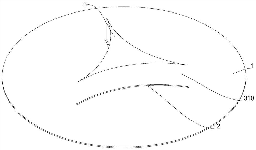
[0029] Such as figure 1 As shown, an antenna includes a circuit board 1, a feeder 2 and a first radiation antenna 3, wherein the feeder 2 is arranged on the circuit board 1, and the first radiation antenna 3 is arranged on the feeder 2, The first radiating antenna 3 is a columnar structure, and the side of the first radiating antenna 3 is provided with three arc-shaped concave surfaces 310, the three arc-shaped concave surfaces 310 are located in different orientations, and any arc-shaped concave surface 310 in the three arc-shaped concave surfaces 310 All are circumscribed simultaneously with the remaining two arcuate concave surfaces 310 , and the lengths of the three arcuate concave surfaces 310 are equal to the length of the first radiation antenna 3 .

Embodiment 2

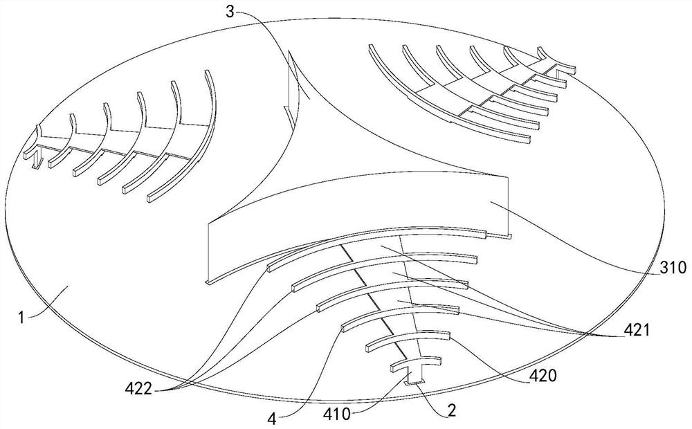
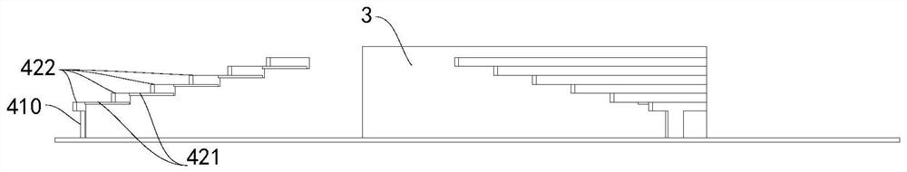
[0031] Such as figure 2 , image 3 As shown, the difference between this embodiment and Embodiment 1 is that the antenna also includes a second radiation antenna 4, and the circuit board 1 is provided with a second radiation antenna 4 corresponding to each curved concave surface 310, that is, the circuit board 1 Three second radiating antennas 4 are arranged on the top, and the three second radiating antennas 4 respectively correspond to the three curved concave surfaces 310 , and all the three second radiating antennas 4 are electrically connected to the feeding part 2 .

[0032] The second radiating antenna 4 includes a column 410 and a radiation portion 420, the column 410 is vertically arranged on the circuit board 1, and the lower end of the column 410 is electrically connected to the feeder 2, and the upper end of the column 410 is connected to the radiation portion 420, and the radiation portion 420 Fan-shaped structure.

[0033] The center of the radiation portion 4...


PUM


Abstract

The invention relates to an antenna which comprises a feed part arranged on a circuit board and a first radiating antenna arranged on the feed part, the first radiating antenna is of a columnar structure, and three arc-shaped concave surfaces which are externally tangent to one another are arranged on the side face of the first radiating antenna. The antenna has the beneficial effects that the three arc-shaped concave surfaces which are externally tangent with one another are arranged on the first radiating antenna, so that the antenna can obtain an ideal directional radiation characteristic, meanwhile, the electromagnetic wave resonance intensity is enhanced, the antenna gain is obviously increased, and the return loss is small.

Description

technical field [0001] The present invention relates to the communication field, in particular to an antenna. Background technique [0002] With the in-depth research and development of wireless communication technology, the performance of communication systems has been continuously improved, and the refined design of antennas has begun to be concerned and valued by researchers to meet the various needs of new application features and performance improvements. For current and future mobile devices, the development trend is that the volume is getting smaller and smaller, and the appearance is more and more beautiful, while the performance must be maintained or even improved. This puts forward strict and even harsh requirements for antenna design. poor. Contents of the invention [0003] The technical problem to be solved by the present invention is to provide an antenna to overcome the above-mentioned deficiencies in the prior art. [0004] The technical solution of the p...

Claims


Application Information

Patent Timeline
Patent Type & Authority Applications(China)
IPC IPC(8): H01Q1/36H01Q1/50
CPCH01Q1/36H01Q1/50
Inventor 孟祥娣
Owner WUHAN BAIQI TECH CO LTD
Why Eureka
Try Eureka