Aperture array antenna based on medium integration ridge waveguide
A technology of slot array antenna and medium integration, applied in the field of slot array antenna, can solve the problems of limited application range and small antenna bandwidth, and achieve the effect of low profile, high gain, and increased number of slots
- Summary
- Abstract
- Description
- Claims
- Application Information
AI Technical Summary
Problems solved by technology
Method used
Image
Examples
specific Embodiment approach 1
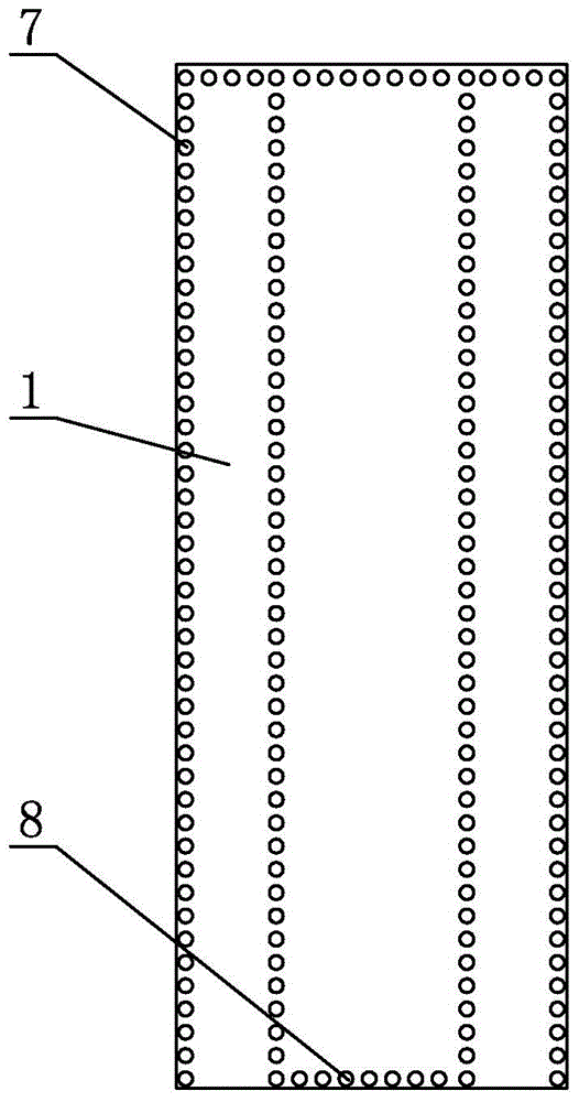
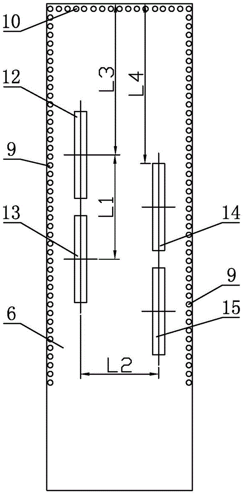
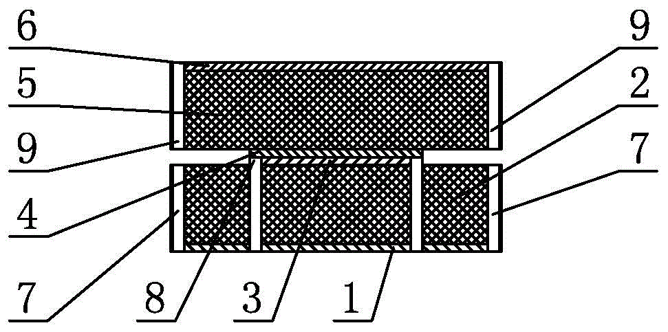
[0007] Specific implementation mode one: combine Figure 1 to Figure 4 Describe this embodiment mode, a slot array antenna based on a dielectric integrated ridge waveguide described in this embodiment mode includes a bottom metal layer 1, a first dielectric plate 2, a first ridge metal layer 3, a second ridge metal layer 4, a second dielectric The plate 5 and the seam metal layer 6, the first dielectric plate 2 and the second dielectric plate 5 are rectangular plates, the first ridge metal layer 3 is a rectangular metal sheet, the bottom metal layer 1, the first dielectric plate 2, the first ridge metal Layer 3, the second ridge metal layer 4, the second dielectric plate 5, and the seam metal layer 6 are stacked sequentially from bottom to top, the first ridge metal layer 3 is located in the middle of the first dielectric plate 2, and the first ridge metal layer 3 is along the The center line of the length direction coincides with the center line of the first dielectric board ...
specific Embodiment approach 2
[0008] Specific implementation mode two: combination Figure 1 to Figure 4 To illustrate this embodiment, the length of the bottom metal layer 1 of a slot array antenna based on a dielectric integrated ridge waveguide described in this embodiment is 110 mm, the width of the bottom metal layer 1 is 42 mm, and the thickness of the bottom metal layer 1 is 0.017 mm to 0.017 mm. 0.035mm.
[0009] The technical effect of this embodiment is that the setting of the length and width can reduce the area of the antenna as much as possible to realize the miniaturization of the antenna, and the setting of the thickness of the metal layer can ensure the reduction of resistance loss. Other components and connections are the same as those in the first embodiment.
specific Embodiment approach 3
[0010] Specific implementation mode three: combination Figure 1 to Figure 4 Describe this embodiment, the length of the first dielectric plate 2 of the slot array antenna based on the dielectric integrated ridge waveguide described in this embodiment is 110 mm, the width of the first dielectric plate 2 is 42 mm, and the thickness of the first dielectric plate 2 is 1.45mm˜1.53mm, and the relative permittivity of the first dielectric plate 2 is 4.4˜4.6.
[0011] The technical effect of this embodiment is: the common FR-4 substrate material is selected for the dielectric plate, and the relative permittivity of this material is relatively large, which facilitates the miniaturization of the antenna; in addition, the selected thickness dimension is also a common FR-4 The size of the 4-type plate is convenient for mass production of the antenna. Other compositions and connections are the same as those in Embodiment 1 or 2.
PUM
 Abstract
Description
Claims
Application Information
 - R&D
- Intellectual Property
- Life Sciences
- Materials
- Tech Scout
- Unparalleled Data Quality
- Higher Quality Content
- 60% Fewer Hallucinations
Browse by: Latest US Patents, China's latest patents, Technical Efficacy Thesaurus, Application Domain, Technology Topic, Popular Technical Reports.
© 2025 PatSnap. All rights reserved.Legal|Privacy policy|Modern Slavery Act Transparency Statement|Sitemap|About US| Contact US: help@patsnap.com


