RFID tag antenna for metal surface

A technology of RFID tags and metal surfaces, applied in the field of RFID tag antennas, can solve the problems of high cost and complex structure, and achieve the effect of low cost, small size and reduced price

Inactive Publication Date: 2013-01-09
SHANGHAI JIAOTONG UNIV
View PDF3 Cites 0 Cited by
  • Summary
  • Abstract
  • Description
  • Claims
  • Application Information

AI Technical Summary

Problems solved by technology

[0006] However, the above solutions are often expensive because of the complex structure, and there is no solution suitable for 840MHz-845MHz, 920MHz-925MHz, which is China's UHF frequency band

Method used


Image

  • RFID tag antenna for metal surface
  • RFID tag antenna for metal surface
  • RFID tag antenna for metal surface

Examples


Embodiment Construction

[0024] The embodiments of the present invention are described in detail below. This embodiment is implemented on the premise of the technical solution of the present invention, and detailed implementation methods and specific operating procedures are provided, but the protection scope of the present invention is not limited to the following implementation example.

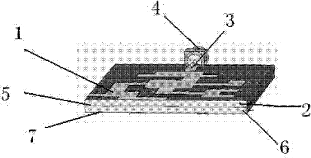
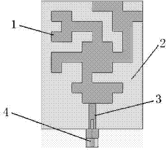
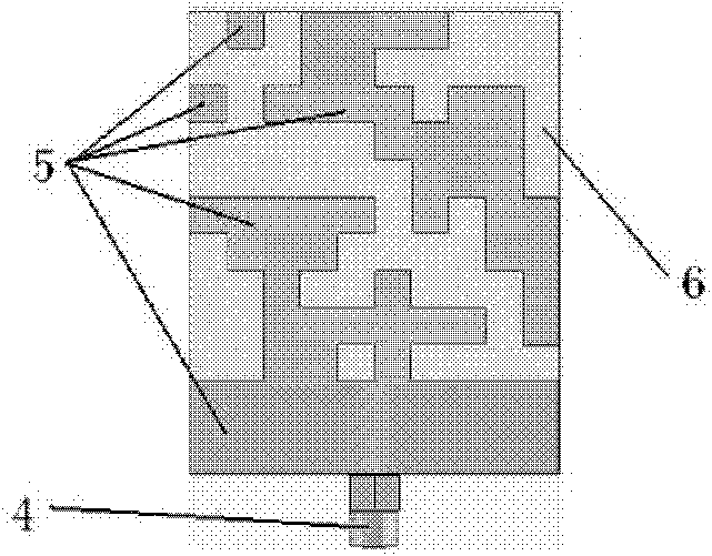
[0025] Such as figure 1 As shown, this embodiment includes: a patch antenna part 1, an upper dielectric board 2, an excitation line 3, a feed port 4, an intermediate ground 5, a lower dielectric board 6 and a lower metal plate 7, wherein: the patch antenna part 1 Located on the upper surface of the upper dielectric plate 2, the intermediate indirect floor 5 is located between the lower dielectric plate 6 and the upper dielectric plate 2, the intermediate indirect floor 5 and the lower metal plate 7 are located on different surfaces of the lower dielectric plate 6, and the intermediate indirect floor 5 is grounded. ...


PUM


Abstract

A RFID tag antenna for a metal surface belongs to the technical field of radio frequency, which comprises a patch antenna part, an upper layered dielectric plate, an excited line, a middle grounding plate, a lower layered dielectric plate, a lower layered metal plate and a feeding port, wherein the patch antenna part is positioned on the upper surface of the upper layered dielectric plate; the middle grounding plate is positioned between the lower layered dielectric plate and the upper layered dielectric plate; the middle grounding plate and the lower layered metal plate are positioned on different surfaces of the lower layered metal plate; the middle grounding plate is grounded; the feeding port is arranged on and connected with the center of the inlet end of the excited line; and one end of the excited line is connected with the patch antenna part, and the other end thereof is connected with the feeding port. The invention is applicable to 840MHz to 845MHz, adopts the double-layer structure to ensure the normal working on the metal surface, and also adopts the common plate, thus greatly reducing the production cost. The antenna of the invention has good directed radiation characteristic, compact structure, small size and long radiation and receiving distance.

Description

technical field [0001] The present invention relates to an antenna device in the technical field of telecommunications, in particular to an RFID (Radio Frequency Identification, radio frequency identification technology) tag antenna for metal surfaces. Background technique [0002] Radio frequency identification technology is a wireless communication technology that uses radio frequency signals to conduct non-contact two-way communication, automatically identify target objects and obtain relevant information data, which emerged in the 1990s. Compared with traditional barcode technology, this technology has seven advantages: fast scanning, small size, multiple shapes, high reuse rate, strong penetration, large data memory capacity, high security, and barrier-free reading. Among them, the RFID tag antenna is one of the key technologies of radio frequency. When the ordinary RFID tag antenna is close to the metal surface, due to the opposite induced current in the metal, the ef...

Claims


Application Information

Patent Timeline
Patent Type & Authority Patents(China)
IPC IPC(8): H01Q1/22H01Q13/00
Inventor 陶晓晖耿军平金荣洪梁仙灵王文智闫鹏
Owner SHANGHAI JIAOTONG UNIV
Why Eureka
Try Eureka