A Miniaturized Directional Radiation Printed Antenna

A printed antenna and directional radiation technology, which is applied in the field of electronic communication, can solve the problems of small size and difficult directional radiation characteristics, and achieve the effects of facilitating integration, enhancing forward radiation gain, and reducing size

Active Publication Date: 2016-04-13
JIANGSU HENGXIN TECH CO LTD
View PDF4 Cites 0 Cited by
  • Summary
  • Abstract
  • Description
  • Claims
  • Application Information

AI Technical Summary

Problems solved by technology

[0004] The purpose of the present invention is to provide a miniaturized directional radiation printed antenna, which aims to solve the problem that it is difficult to have both directional radiation characteristics and the advantages of small size in the design of portable mobile terminal equipment antennas, and it cannot satisfy both equipment integration and Ergonomic Design Needs Questions

Method used


Image

  • A Miniaturized Directional Radiation Printed Antenna

Examples


Embodiment Construction

[0013] In order to make the object, technical solution and advantages of the present invention clearer, the present invention will be further described in detail below in conjunction with the accompanying drawings and embodiments. It should be understood that the specific embodiments described here are only used to explain the present invention, not to limit the present invention.

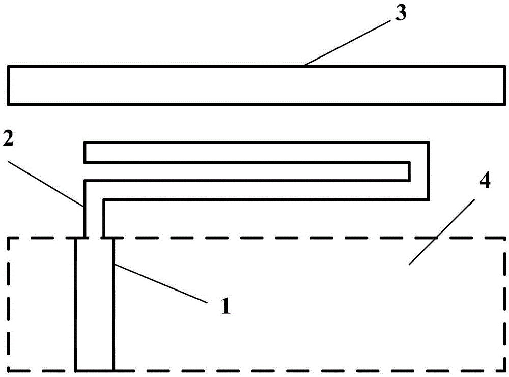
[0014] figure 1 It shows the structure of a miniaturized directional radiation printed antenna of the present invention, including: feeding conductive trace 1, double-folded inverted L-shaped conductive trace 2, parasitic radiation unit 3, and metal floor 4; double-folded inverted L The lower end of the shaped conductive trace 2 is connected to the feeding conductive trace 1, and at the center axis of the space above the double-folded inverted L-shaped conductive trace 1, an independent narrow and elongated parasitic radiation unit 3 with a length of about one-third of the working wavelength is int...


PUM


Abstract

The invention discloses a miniaturized directed radiation printed antenna. The lower end of a double-folded reverse-L-shaped conductive trace is connected with a feed and conductive trace, a parasitic radiation unit is arranged in the space over the double-folded reverse-L-shaped conductive trace, and a metal floor is arranged on the back face of the feed and conductive trace. According to the double-folded reverse-L-shaped conductive trace, a metal wire with the length equal to three fourths of a working wavelength is repeatedly bent to form a space electromagnetic field excitation structure provided with two sections of long conductors mutually in parallel. By the adoption of the double-folded reverse-L-shaped space excitation structure, the ideal directed radiation characteristic can be obtained, the parasitic radiation unit is added, so that radiation gains of the antenna in the forward direction are increased, a space mutual-coupling principle is utilized, an antenna closely-spaced technology is adopted, so that space is compressed and the size of the antenna is reduced, and a planar antenna printing technology is adopted, so that a radiation body and the ground are located in planes which are mutually in parallel, equipment space is fully utilized, and integration of the antenna and a circuit board is facilitated.

Description

technical field [0001] The invention belongs to the technical field of electronic communication, in particular to a miniaturized directional radiation printed antenna. Background technique [0002] With the in-depth research and development of wireless communication technology, the performance of communication systems has been continuously improved, and the refined design of antennas has begun to be concerned and valued by researchers to meet the various needs of new application features and performance improvements. For current and future mobile terminal equipment, the development trend is that the volume will become smaller and smaller, and the appearance will become more and more beautiful, while the performance must be maintained or even improved, which puts strict and even harsh requirements on the antenna design. In traditional antenna design, based on the basic antenna prototype, reducing the size of the antenna will be at the expense of other performances of the ante...

Claims


Application Information

Patent Timeline
Patent Type & Authority Patents(China)
IPC IPC(8): H01Q1/38
Inventor 杨熙刘瑶胡伟郑书峰尹应增
Owner JIANGSU HENGXIN TECH CO LTD
Why Eureka
Try Eureka