Heat dissipation control method and device of electric control box and air conditioner
A control method and technology of electric control box, applied in the direction of electrical components, electrical equipment structural parts, cooling/ventilation/heating transformation, etc., can solve the problem of large heat dissipation power consumption of electric control box, and achieve the effect of reducing heat dissipation power consumption
- Summary
- Abstract
- Description
- Claims
- Application Information
AI Technical Summary
Problems solved by technology
Method used
Image
Examples
Embodiment 1
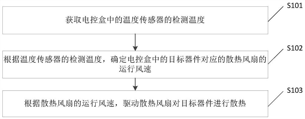
[0058] figure 2 A schematic flow chart of a heat dissipation control method for an electric control box provided in an embodiment of the present application, as shown in figure 2 As shown, it is a specific method of how to dissipate heat from the electric control box provided by the embodiment of the present application, and the execution subject of this embodiment is the controller. Such as figure 2 As shown, the heat dissipation control method of the electric control box includes:
[0059] S101. Obtain the detection temperature of the temperature sensor in the electric control box.
[0060] In this application, if it is detected that the compressor in the air conditioner starts to run, the electric control box in the air conditioner will perform work accordingly. At this time, it is necessary to obtain the detection temperature of the temperature sensor in the electric control box, so as to The temperature detected by the sensor drives the cooling fan in the electric c...
Embodiment 2
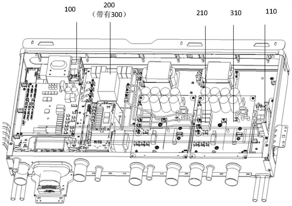
[0090] image 3 It is a schematic structural diagram of an electric control box provided in an embodiment of the present application. Such as image 3 As shown, the first heat dissipation fan 100 and the second heat dissipation fan 110 are arranged inside the electric control box. A temperature sensor 1 300 is disposed on the common mode inductor 200 , and a temperature sensor 2 310 is disposed on the template block 210 .
[0091] Wherein, the cooling fan-100 is used to dissipate heat from the common-mode inductor 200, the temperature sensor-300 is used to collect the detected temperature of the common-mode inductor 200, and the detected temperature of the temperature sensor-300 is used to reflect the common-mode inductor 200 or the cooling fan-100 operating status. The second cooling fan 110 is used to dissipate heat from the template block 210 , the second temperature sensor 310 is used to collect the detected temperature of the template block 210 , and the detected tempe...
Embodiment 3
[0124] Figure 5 It is a schematic structural diagram of another electric control box provided in the embodiment of this application. Such as Figure 5 As shown, cooling fan 3 120 and cooling fan 4 130 are arranged inside the electric control box, and cooling fan 3 120 and cooling fan 4 130 are arranged near target devices, such as inductors, electrolytic capacitors, and non-inductive resistors. A cavity temperature sensor 320 is arranged in the cavity of the electric control box.
[0125] Wherein, the cavity temperature sensor 320 is used to collect the overall temperature in the electric control box, and the heat dissipation fan 3 120 and the heat dissipation fan 4 130 are used to dissipate heat from the components in the electric control box.
[0126] exist Figure 5 On the basis of the structure of the electric control box shown, the corresponding heat dissipation control method of the electric control box is provided below. Image 6 A schematic flow chart of another h...
PUM
 Abstract
Description
Claims
Application Information
 - R&D
- Intellectual Property
- Life Sciences
- Materials
- Tech Scout
- Unparalleled Data Quality
- Higher Quality Content
- 60% Fewer Hallucinations
Browse by: Latest US Patents, China's latest patents, Technical Efficacy Thesaurus, Application Domain, Technology Topic, Popular Technical Reports.
© 2025 PatSnap. All rights reserved.Legal|Privacy policy|Modern Slavery Act Transparency Statement|Sitemap|About US| Contact US: help@patsnap.com


