
Modular wind power blade and assembling method thereof

A technology for wind turbine blades and assembly methods, which is applied to the assembly of wind turbines, wind power generation, and wind turbines in the same direction as the wind, and can solve problems such as high cost, difficulty and cost of mold and equipment manufacturing, and difficulty in manufacturing and assembling , to achieve the effects of reduced transportation difficulty, low risk of connection failure, and low transportation cost

Active Publication Date: 2021-11-23
NEWTECH GRP CO LTD
View PDF7 Cites 7 Cited by
  • Summary
  • Abstract
  • Description
  • Claims
  • Application Information

AI Technical Summary

Problems solved by technology

[0004] This situation leads to the continuous improvement of the manufacturing conditions of the integral blade, and the difficulty and cost of manufacturing molds and equipment are getting higher and higher; while the manufacturing and assembly of the combined blade in the past is difficult, the site equipment occupation is the same as that of the integral blade, and the cost is relatively high. High, so not accepted by the market

Method used


Image

  • Modular wind power blade and assembling method thereof
  • Modular wind power blade and assembling method thereof
  • Modular wind power blade and assembling method thereof

Examples


Embodiment Construction

[0058] The following will clearly and completely describe the technical solutions in the embodiments of the present invention with reference to the accompanying drawings in the embodiments of the present invention. Obviously, the described embodiments are only some, not all, embodiments of the present invention.

[0059] It should be noted that when an element is referred to as being "fixed" to another element, it can be directly on the other element or there may be an intervening element. When an element is said to be "connected" to another element, it can be directly connected to the other element or intervening elements may also be present. The terms "vertical," "horizontal," "left," "right," and similar expressions are used herein for purposes of illustration only and are not intended to represent exclusive embodiments.

[0060]Unless otherwise defined, all technical and scientific terms used herein have the same meaning as commonly understood by one of ordinary skill in t...


PUM


Abstract

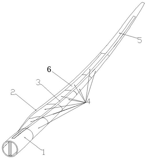
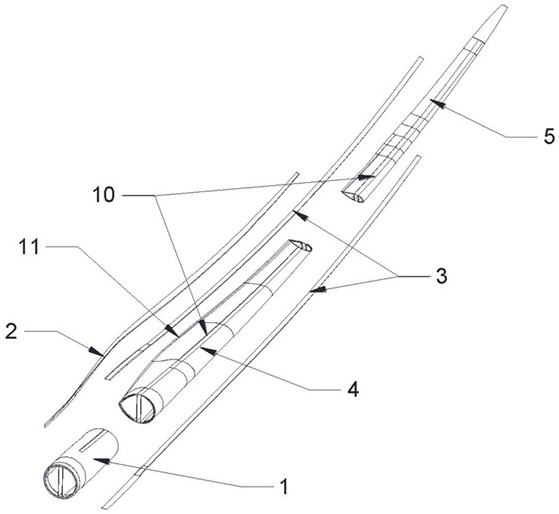
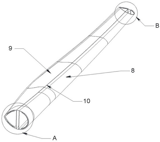
The invention relates to the technical field of wind power blades, and particularly relates to a modular wind power blade and an assembling method thereof. The wind power blade comprises a blade body, a main beam module and a rear edge beam module; the blade body is provided with a suction surface, a pressure surface, a blade root end, a blade tip end, a blade front edge and a blade rear edge; the blade body is divided into a blade root module, a blade middle module and a blade tip module in the length direction of the blade; a first groove and a second groove which extend in the length direction of the blade are formed in the outer surface of the blade root module, the outer surface of the blade middle module and the outer surface of the blade tip module together; the first groove is located in a main beam area of the suction surface and the pressure surface; the main beam module is mounted in the first groove through a bonding or vacuum pouring process; the second groove is located in the blade rear edge and located in the butt joint position of the suction surface and the pressure surface; and the rear edge beam module is mounted in the second groove through a bonding or vacuum pouring process. The wind power blade provided by the invention is convenient to produce in a distributed and automatic mode, easy to assemble and convenient to transport.

Description

technical field [0001] The invention relates to the technical field of wind power blades, in particular to a modular wind power blade and an assembly method thereof. Background technique [0002] The blades of wind turbines are generally integral fiberglass blades. At the same time, there are also some combined blades of different forms at home and abroad. Most of the cases are based on the main beam structure. The shell is split according to different sizes, and then glued Assembled to the main girder in the form of joint or mechanical connection. [0003] With the rise of the megawatt level of generating units and the gradual exhaustion of excellent resources, wind farms are currently expanding from plains to hills, from land to ocean, and the size and weight of blades are also increasing. [0004] This situation leads to the continuous improvement of the manufacturing conditions of the integral blade, and the difficulty and cost of manufacturing molds and equipment are g...

Claims


Application Information

Patent Timeline
Patent Type & Authority Applications(China)
IPC IPC(8): F03D1/06F03D13/10
CPCF03D1/0675F03D13/10Y02P70/50
Inventor 谈昆伦白高宇刘叶霖曹磊
Owner NEWTECH GRP CO LTD
Learn More