Mechanical stove air-fuel ratio control device and valve path tapping method thereof

Pending Publication Date: 2021-11-23
ANHUI HANSUM INSTR EQUIP
View PDF0 Cites 0 Cited by
  • Summary
  • Abstract
  • Description
  • Claims
  • Application Information

AI Technical Summary

Problems solved by technology

This control method is widely used. Its advantage is that it can realize the related adjustment of stove firepower and air volume at the same time with one action; Synchronous rotation is also a fixed value, so it cannot meet the demand for precise air-fuel ratio adjustment in a wide range of firepower
③The air volume can be regulated through the frequency conversion speed regulation of the fan AC motor to meet the precise air-fuel ratio under different firepower; but due to the high cost, the frequency conversion speed regulation of the single-phase AC motor with low voltage and low power is uneconomical, and the market application rarely
Due to its technical principle, it has the disadvantages of high cost and the inability to adjust the air-fuel ratio characteristic curve, and it must be maintained once a year, and the workload of after-sales service is relatively large.
This also limits its application

Method used


Image

  • Mechanical stove air-fuel ratio control device and valve path tapping method thereof
  • Mechanical stove air-fuel ratio control device and valve path tapping method thereof
  • Mechanical stove air-fuel ratio control device and valve path tapping method thereof

Examples


Embodiment Construction

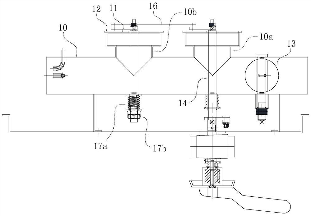
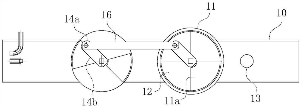
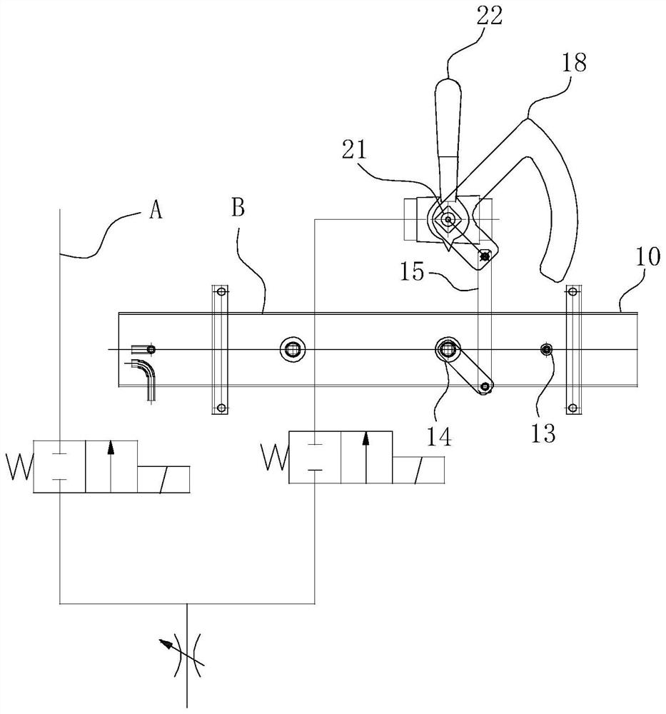
[0041] For ease of understanding, combined here Figure 1-3 , the concrete structure and working mode of the present invention are further described as follows:

[0042] Concrete structure of the present invention refers to Figure 1-2 As shown, during assembly, the present invention realizes the accurate control of the air-fuel ratio by bypassing the air volume of the fan by shunting and releasing pressure; the principle is that the theoretical air volume Q 0 = Air volume Q required by the burner 1 +Bypass shunt air volume Q 2 . When working: the blower fan is located at the front end of the invention so as to communicate with the air inlet, while the burner is located at the rear end of the invention and communicates with the air outlet. The air regulating shaft 21 at the gas valve of the burner and the air regulating shaft 14 at the main flow distribution and pressure relief pipe 10a are synchronously driven through coaxial or sprocket connection or eccentrically hinge...


PUM


Abstract

The invention belongs to the technical field of stove air-fuel ratio control, and particularly relates to a mechanical stove air-fuel ratio control device and a valve path tapping method thereof. The device comprises a main air pipe, a flow dividing pressure relief pipe is arranged on the side wall of the main air pipe, a sealing plate is arranged at the air outlet end of the flow dividing pressure relief pipe, and an air relief hole communicating with the flow dividing pressure relief pipe and a pipe cavity of the main air pipe is formed in the sealing plate in a penetrating mode; and the device further comprises a flow dividing baffle attached to the sealing plate face, and therefore the air flux of the air leakage holes is adjusted through the transverse movement or rotation action of the flow dividing baffle relative to the air leakage holes in the sealing plate. The device not only can meet the requirement for accurate air-fuel ratio adjustment under different fire powers, but also has the advantages of being simple and compact in structure, reliable and stable in work, long in service life and low in cost. The other purpose of the invention is to provide a valve path tapping method based on the mechanical stove air-fuel ratio control device, so that the working reliability of the flow dividing pressure relief pipe is realized specifically through a simple and rapid mechanical tapping mode.

Description

technical field [0001] The invention belongs to the technical field of stove air-fuel ratio control, and in particular relates to a mechanical stove air-fuel ratio control device and a valve circuit opening method thereof. Background technique [0002] In order to improve the combustion efficiency of commercial stoves, an appropriate air-fuel ratio is extremely critical. The domestic commercial stove industry usually adopts the following operation methods: ① Independently adjust the flow of gas and air volume. The disadvantage of this method is that the air-fuel ratio cannot be adjusted accurately and the operation is inconvenient. ②The gas valve at the gas valve and the damper in the main air duct are adjusted through chain wheel adjustment or coaxial synchronous linkage adjustment, so as to achieve the purpose of synchronous linkage action of the damper by twisting the valve. This control method is widely used. Its advantage is that it can realize the related adjustment o...

Claims


Application Information

Patent Timeline
Patent Type & Authority Applications(China)
IPC IPC(8): F16K11/16F16K11/10F16K37/00F24C3/12F23D14/60
CPCF16K11/166F16K11/10F16K37/0008F24C3/126F23D14/60
Inventor 夏光超
Owner ANHUI HANSUM INSTR EQUIP
Why Eureka
Try Eureka