
Carbon dioxide cascade heat pump system

A carbon dioxide and heat pump system technology, applied in the field of heat pumps, can solve the problem of lack of secondary utilization of energy and achieve the effect of secondary utilization

Inactive Publication Date: 2021-11-23
南京优辉新能源科技有限公司
View PDF0 Cites 0 Cited by
  • Summary
  • Abstract
  • Description
  • Claims
  • Application Information

AI Technical Summary

Problems solved by technology

[0005] In order to solve the technical problem that the energy consumed in the existing carbon dioxide cascade heat pump system can only be used for heating and lacks the secondary utilization of energy, the present invention provides a carbon dioxide cascade heat pump system to effectively realize the secondary utilization of energy use

Method used


Image

  • Carbon dioxide cascade heat pump system
  • Carbon dioxide cascade heat pump system
  • Carbon dioxide cascade heat pump system

Examples


Embodiment Construction

[0019] The specific implementation manners of the present invention will be clearly and completely described and illustrated below in conjunction with the accompanying drawings.

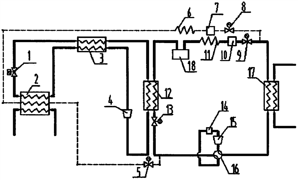
[0020] figure 1 It is a schematic diagram of the principle of the carbon dioxide cascade heat pump system of the present invention.

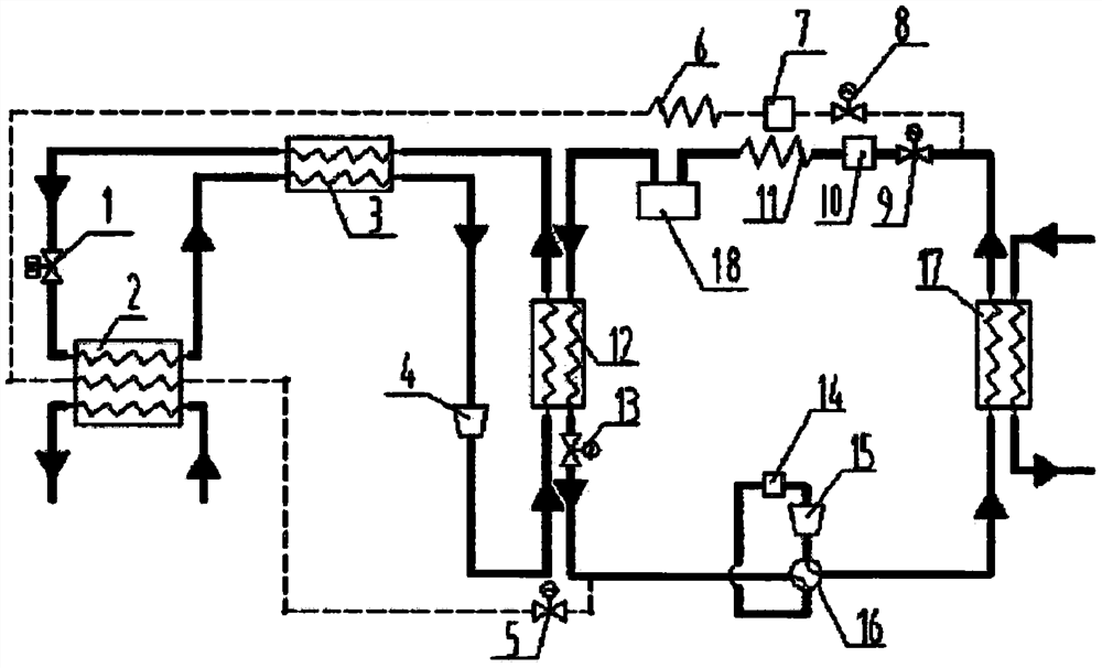
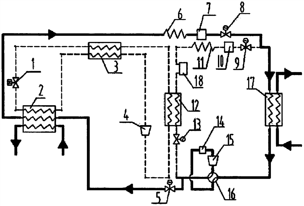
[0021] like figure 1 As shown, the carbon dioxide cascade heat pump system of the present invention includes a common heat pump refrigeration cycle and a carbon dioxide heat pump refrigeration cycle.

[0022] Among them, the ordinary heat pump refrigeration cycle includes a first capillary tube 11, an ice maker 18, and an evaporative condenser 12 arranged in sequence. The valve 16 communicates with the heat exchanger 17 and the first capillary 11 in sequence.

[0023] Compared with the prior art, the carbon dioxide cascade heat pump system of the present invention, since an ice maker 18 is provided between the first capillary tube 11 and the evaporative condenser 12...


PUM


Abstract

The invention provides a carbon dioxide cascade heat pump system. The carbon dioxide cascade heat pump system comprises a common heat pump refrigeration cycle and a carbon dioxide heat pump refrigeration cycle. The common heat pump refrigeration cycle comprises a first capillary tube (11), an ice maker (18) and an evaporative condenser (12) which are sequentially arranged; the evaporative condenser (12) communicates with a first compressor (15) through a reversing valve (16); and the first compressor (15) sequentially communicates with a heat exchanger (17) and the first capillary tube (11) through the reversing valve (16). The carbon dioxide heat pump refrigeration cycle comprises an expansion valve (1), an outdoor heat exchanger (2), an internal heat exchanger (3), a second compressor (4) and an evaporative condenser (12) which are sequentially arranged; and the evaporative condenser (12) communicates with the expansion valve (1) through the internal heat exchanger (3). The carbon dioxide heat pump refrigeration cycle and the common heat pump refrigeration cycle can enable the carbon dioxide cascade heat pump system to achieve the effect of heating in winter and ice making at the same time, and secondary utilization of energy is effectively achieved.

Description

technical field [0001] The invention relates to the technical field of heat pumps, in particular to a carbon dioxide cascade heat pump system, which is especially suitable for extremely cold regions. Background technique [0002] A heat pump is a device that can transfer heat energy from a low-level heat source to a high-level heat source. Usually, it first obtains low-grade heat energy from natural air, water or soil, and then provides high-grade heat energy that can be used by people. . [0003] The carbon dioxide cascade heat pump system can be applied to heating. It has two sets of circulation systems, one is the gas circulation of the low-temperature section through carbon dioxide, and the other is the liquid circulation of the high-temperature section through Freon, etc., and the two sets of circulation The system can be connected together through the evaporative condenser, and the effect of heat exchange and heating can be realized when the evaporative condenser is i...

Claims


Application Information

Patent Timeline
Patent Type & Authority Applications(China)
IPC IPC(8): F25B9/00F25B41/20F25B41/31F25B49/02
Inventor 刘勇
Owner 南京优辉新能源科技有限公司
Learn More