
High-stability transformer with overheating early warning function

Active Publication Date: 2021-11-23
海门市昊天机电配件有限公司
View PDF4 Cites 2 Cited by
  • Summary
  • Abstract
  • Description
  • Claims
  • Application Information

AI Technical Summary

Problems solved by technology

[0003] When the transformer is in operation, it will generate a lot of heat. In the prior art, heat dissipation scales are usually arranged on the surface of the transformer to increase the heat dissipation area and achieve the effect of heat dissipation. In actual use, there is an abnormal situation of excessive temperature. If it is not discovered in time and corresponding measures are not taken in time, it will easily affect the safe and stable operation of the transformer, and even have certain potential safety hazards.

Method used


Image

  • High-stability transformer with overheating early warning function
  • High-stability transformer with overheating early warning function
  • High-stability transformer with overheating early warning function

Examples


Embodiment 1

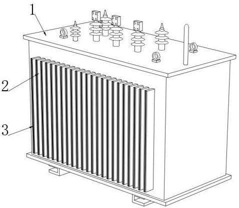
[0036] See figure 1 A high stability transformer of overheating warning, including transformer body 1, and a plurality of uniform distributed heat dissipation flakes 2 are connected outside the outer end of the transformer body 1, and a concentrating strip 3 is provided toward the outer end.

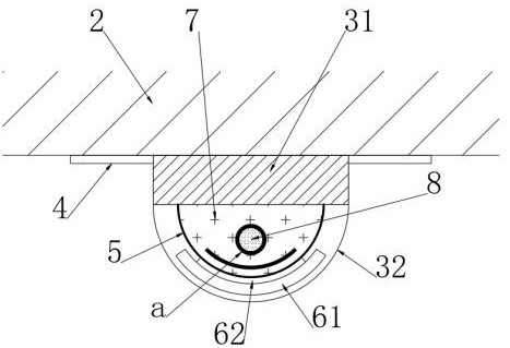
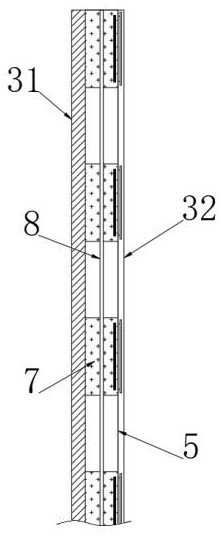
[0037] See figure 2 The outer end of the concentrating strip 3 is fixedly coupled to the adhesive film 4, the helper bottom sheet 4 and the heat dissipation flake 2 are bonded, and the concentrating strip 3 includes a heat absorbing layer 31 and a light-changing color layer fixed to the heat absorbing layer 31. 32. The heat absorbing layer 31 is attached to each other, and the heat shifting layer 31, the photoreactive color layer 32, and the bonding surface 4 are made of high thermal conductivity materials, so that the setting of the concentrating strip 3 is not easy to affect the transformer body. 1 The upper air is overflowing, it is not easy to cause heat dissipation, and the thermal bloc...

Embodiment 2

[0043] Based on the embodiment, the following is also set:

[0044] See Figure 8 The outer rosin is connected to the outer end portion of the photointestinal color layer 32, and the outer rosin includes a plurality of positioning blocks 101 fixed to the light-changing color layer 32, and the plurality of connections are adjacent two positioning blocks 101. The magnetic ridge 102 and the magnetic point 103 connected in the middle of the magnetic ridge 102, and the positioning block 101 is opened to each other, and the inner tank is fixed, and the angle of the magnetic ridge 102 is fixed to the inner wall of the inline. Further, the portion of the magnetic ridge 102 is located in the insertion tank is a helical, and the magnetic ridge 102 is located outside the positioning block 101 is a flat straight shape, and the magnetic point 103 is made of a magnetic material, and magnetic point 103 is magnetic. There is a magnetifier force between the block 9, and the magnetic ridge 102 is a ...


PUM

PropertyMeasurementUnit
Melting temperatureaaaaaaaaaa

Abstract

The invention discloses a high-stability transformer with an overheating early warning function, which belongs to the field of transformers. Through the arrangement of a light condensation strip, when the transformer is overheated, a thermal drop ring between a thermal moving block and a thermal coating pre-change rod is subjected to hot melting, so that the thermal moving block is unfixed, and the thermal moving block drives a magnetic moving light sheet to move downwards and gather together, the original light condensation strip with interval light emitting presents the phenomenon of bottom condensation light emitting, thereby realizing the overheating early warning effect for workers, and in addition, along with downward movement of the thermal moving block, the hot-melt thermal drop ring is gradually coated on the thermal coating pre-change rod, so that the color strip phenomenon is presented above the light emitting part. Due to double changes, the overheating early warning effect on workers is better, what is effectively guaranteed is that overheating is handled in time, the stability of the transformer is remarkably improved, and potential safety hazards possibly caused by overheating are greatly reduced.

Description

Technical field [0001] The present invention relates to the field of transformers, and more particularly to a high stability transformer of an overheating warning. Background technique [0002] Transformer is a device that uses electromagnetic induction to change the AC voltage, the main member is the primary coil, the secondary coil, and the core (magnetic core). Transformer cooling refers to dissipation of heat generated by the transformer in operation by a certain method. When the transformer is running, the heat generated by the loss in the windings and core must be ejected in time to avoid overheating. For small-capacity transformers, the outer surface area and the transformer volume are relatively large, and the heat can be used in a cold mode, and the heat can be dispersed by radiation and natural conveying. [0003] When the transformer is running, a large amount of heat is generated. In the prior art, the heat dissipation scales are typically set on the surface of the tr...

Claims


Application Information

Patent Timeline
IPC IPC(8): H01F27/22H01F27/40G08B5/02G08B21/18
Inventor 施金辉
Owner 海门市昊天机电配件有限公司
Learn More