Integrated circuit processing method and processing equipment

A technology for integrated circuits and processing equipment, which is applied in the field of integrated circuit processing methods and processing equipment, can solve problems such as inaccurate welding positions, lack of welding, and difficult positioning, and achieve the goal of avoiding inaccurate positions, preventing lack of welding and missing welding Effect

Pending Publication Date: 2021-11-23
谢利洪
View PDF0 Cites 0 Cited by
  • Summary
  • Abstract
  • Description
  • Claims
  • Application Information

AI Technical Summary

Problems solved by technology

[0002] The integrated circuit board uses semiconductor manufacturing technology to manufacture many transistors, resistors, capacitors and other components on a small single crystal silicon chip, and combines the components into a complete circuit board according to the method of multi-layer wiring or tunnel wiring. Electronic circuits, in the process of integrated circuit processing, need a variety of processes, soldering is one of them, and now mass production has been used for mechanical soldering, but the existing integrated circuits are mechanically soldered. Adjusting the mechanical arm of the machine or the integrated circuit board, and performing single-point welding on the integrated circuit board is not only difficult in positioning, but also prone to inaccurate welding positions, lack of welding and missing welding, and the welding efficiency is low during the single-point welding process, so There is an urgent need for an integrated electrical processing method and processing equipment to meet the needs of actual mass production of integrated circuits

Method used


Image

  • Integrated circuit processing method and processing equipment
  • Integrated circuit processing method and processing equipment
  • Integrated circuit processing method and processing equipment

Examples


Embodiment 1

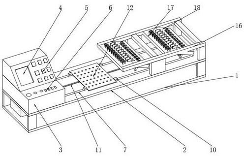
[0034] Refer to the attached Figure 1-8, an integrated circuit processing method and processing equipment, comprising a base 1, the top of the base 1 is fixed with a positioning board 2 by a bracket, the top side of the positioning board 2 is fixed with a console 3, and the top of the positioning board 2 is fixed by a bracket Two tin wire fixing plates 16 are provided, and the inner walls of the two tin wire fixing plates 16 are fixedly provided with two soldering plates 17, and the outer wall of one side of the soldering plate 17 is fixedly provided with an inclined downward soldering plate 18. The top outer wall of the welding plate 18 has a fixing groove 24, the inner wall of the fixing groove 24 is fixedly provided with a fixing sleeve 25, the inner wall of the fixing sleeve 25 is inserted with a lead sleeve 26, and the inner wall of the fixing sleeve 25 is inserted with a lead sleeve 26 is convenient to replace and maintain the article in the lead sleeve 26, and the top ...

Embodiment 2

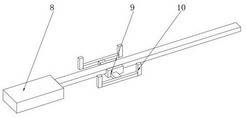
[0036] On the basis of Embodiment 1, a chute 11 is provided at the central position of the top of the positioning plate 2, sliding channels 7 are provided on both sides of the top of the positioning plate 2, and a linear motor 8 and a linear motor 8 are fixedly arranged on the outer wall of the bottom of the positioning plate 2. The output block is fixed with a slider 9, the outer wall of the slider 9 is fixed with four positioning blocks 10 through the bracket, the outer walls of the four positioning blocks 10 are slidingly connected with the inner walls of the two sliding passages 7, and the top of the positioning plate 2 The outer wall is provided with a positioning plate 12, and the top outer wall of the positioning plate 12 has positioning holes 13 distributed equidistantly. , one side outer wall of the four positioning blocks 10 is fixedly connected with the outer wall of the positioning plate 12, the output block of the linear motor 8 can drive the slider 9 to move, the ...

Embodiment 3

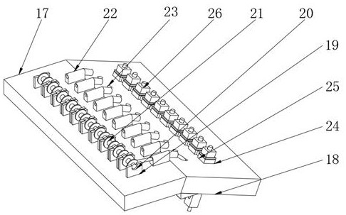
[0038] On the basis of Embodiment 1, the top side of the soldering plate 17 is fixed with fixed pieces 19 distributed equidistantly. The arc-shaped fixing groove 20 is sleeved with a tin wire reel 21, the outer wall of the tin wire reel 21 is wound with a tin wire main body 35, and the top side of the solder plate 17 is fixed with guide sleeves 22 distributed equidistantly. The top side of 18 is provided with the guide hole 23 of equidistant distribution, is convenient to guide the tin wire main body 35 that the outer wall of tin wire reel 21 is wound around through guide sleeve 22 and guide hole 23, and the top side of lead wire sleeve 26 is fixedly provided with Positioning bar 27, the inwall of lead wire sleeve 26 is fixedly provided with micro electric telescopic motor 30, the output block of micro electric telescopic motor 30 is fixedly provided with push block 31, and the bottom central position of lead wire sleeve 26 has outlet port 28, and the outlet The inner wall of ...


PUM


Abstract

The invention discloses an integrated circuit processing method and equipment, and the equipment comprises a pedestal, the top of the pedestal is fixedly provided with a positioning plate through a support, one side of the top of the positioning plate is fixedly provided with a console, and the top of the positioning plate is fixedly provided with two solder wire fixing plates through a support. Two tin soldering plates are fixedly arranged on the inner walls of the two tin wire fixing plates, a downward-inclined tin soldering plate is fixedly arranged on the outer wall of one side of each tin soldering plate, a fixing groove is formed in the outer wall of the top of each tin soldering plate, and a fixing sleeve is fixedly arranged on the inner wall of each fixing groove. The top of the integrated circuit board is welded through cooperation of the multiple lead sleeves and the laser tin melting spotlight, after the integrated circuit board moves on the tin soldering plate and the bottom of the tin soldering plate, top tin soldering of the integrated circuit board is completed, the tin soldering efficiency of the top of the integrated circuit board is greatly improved, the using effect is good, and large-scale batch processing of integrated circuit boards in existing factories is met.

Description

technical field [0001] The invention relates to the field of integrated circuit processing, in particular to an integrated circuit processing method and processing equipment. Background technique [0002] The integrated circuit board uses semiconductor manufacturing technology to manufacture many transistors, resistors, capacitors and other components on a small single crystal silicon chip, and combines the components into a complete circuit board according to the method of multi-layer wiring or tunnel wiring. Electronic circuits, in the process of integrated circuit processing, need a variety of processes, soldering is one of them, and now mass production has been used for mechanical soldering, but the existing integrated circuits are mechanically soldered. Adjusting the mechanical arm of the machine or the integrated circuit board, and performing single-point welding on the integrated circuit board is not only difficult in positioning, but also prone to inaccurate welding ...

Claims


Application Information

Patent Timeline
Patent Type & Authority Applications(China)
IPC IPC(8): H01L21/67H01L21/68H01L21/60
CPCH01L21/67144H01L21/68H01L24/13H01L2224/13
Inventor 谢利洪
Owner 谢利洪
Why Eureka
Try Eureka