Radar antenna lifting mechanism with antenna fixedly connected to connecting rod

A technology of radar antenna and lifting mechanism, which is applied to antennas, folded antennas, rotating antennas, etc., can solve the problems of poor stability and low working reliability, and achieve the effects of good stability, improved working reliability, and easy normal work.

Active Publication Date: 2021-11-23
CHINA ELECTRONIC TECH GRP CORP NO 38 RES INST
View PDF11 Cites 1 Cited by
  • Summary
  • Abstract
  • Description
  • Claims
  • Application Information

AI Technical Summary

Problems solved by technology

[0005] In the prior art, the center of mass of the antenna deviates from the rotating shaft of the turntable after being lifted by the antenna lifting mechanism, which cannot take into account the technical problems of lifting and the center of mass of the antenna being located on the rotating shaft of the turntable during lifting, and the low reliability and poor stability of the antenna for long-term and high-speed operation

Method used


Image

  • Radar antenna lifting mechanism with antenna fixedly connected to connecting rod
  • Radar antenna lifting mechanism with antenna fixedly connected to connecting rod
  • Radar antenna lifting mechanism with antenna fixedly connected to connecting rod

Examples


Embodiment Construction

[0056] In order to make the purpose, technical solutions and advantages of the embodiments of the present invention clearer, the technical solutions in the embodiments of the present invention will be clearly and completely described below in conjunction with the embodiments of the present invention. Obviously, the described embodiments are part of the present invention Examples, not all examples. Based on the embodiments of the present invention, all other embodiments obtained by persons of ordinary skill in the art without creative efforts fall within the protection scope of the present invention.

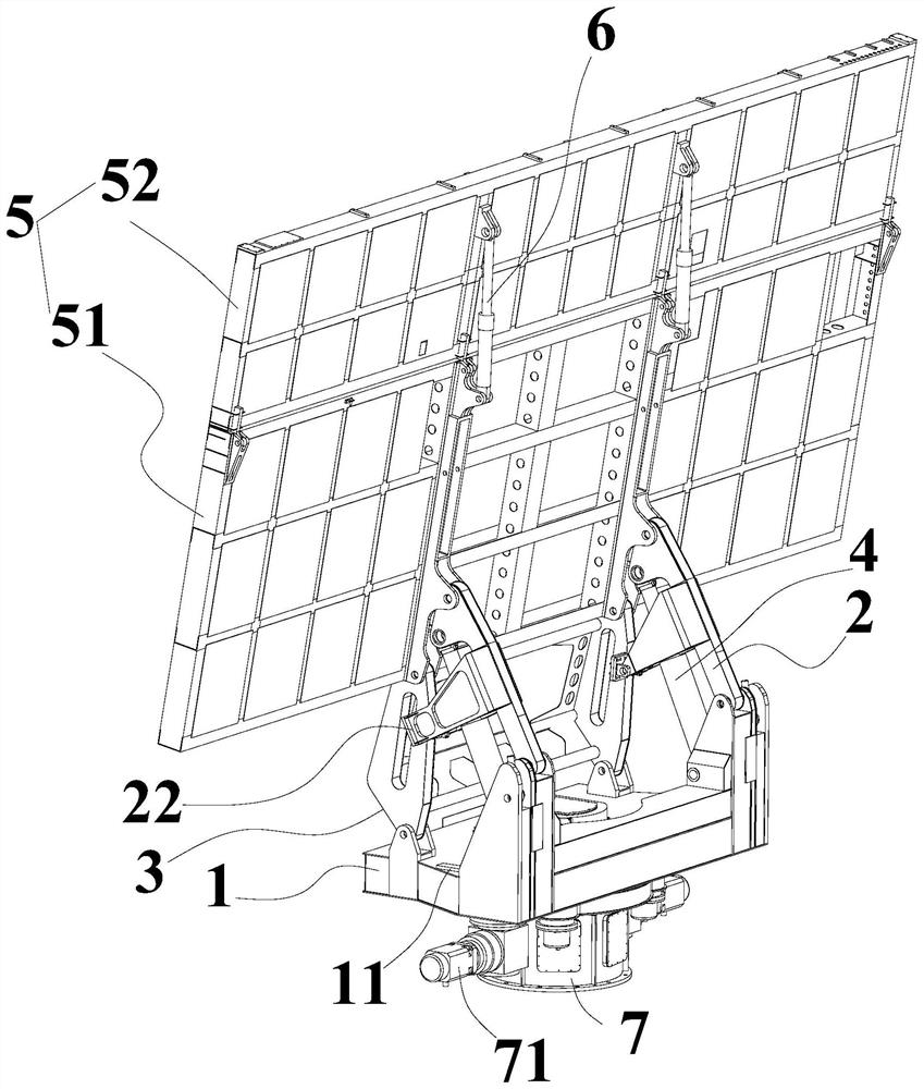
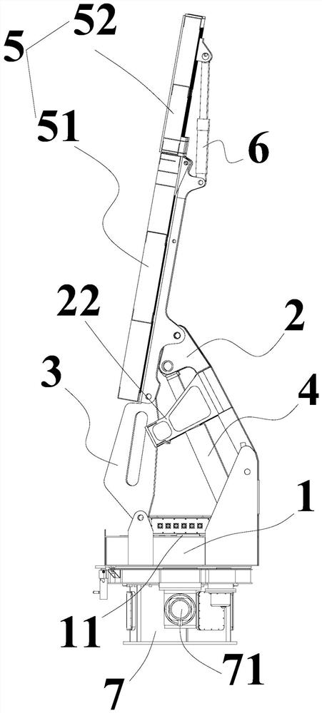
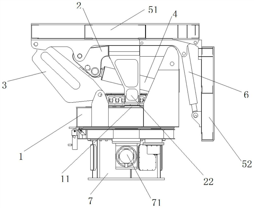
[0057] like figure 1 As shown, a radar antenna lifting mechanism in which the antenna is fixedly connected to the connecting rod includes a turntable 1, a main connecting rod 2, an auxiliary connecting rod 3, a lifting driving mechanism 4, an antenna 5, a turning driving mechanism 6, and a base 7.

[0058] like Figure 7-9 As shown, the turntable 1 is the prior art and can be ...


PUM


Abstract

The invention discloses a radar antenna lifting mechanism with an antenna fixedly connected to a connecting rod. The radar antenna lifting mechanism comprises a rotary table, a main frame connecting rod, an auxiliary frame connecting rod, a lifting driving mechanism and the antenna. The first end of the main connecting frame rod and the first end of the auxiliary connecting frame rod are hinged to the rotary table. The second end of the main frame connecting rod and the second end of the auxiliary frame connecting rod are hinged to the antenna; a four-bar mechanism is formed among the rotary table, the main side link, the antenna and the auxiliary side link; the two ends of the lifting driving mechanism are hinged to the rotary table and the main frame connecting rod respectively. When the antenna is unfolded or retracted, the center of mass of the antenna is located above the rotary shaft of the rotary table. The radar antenna lifting mechanism has the advantages that the antenna is fixedly connected to the connecting rod, lifting can be achieved, lifting can be ensured, meanwhile, the mass center falls on the axis of the rotating shaft, and the mass center of the antenna is located above the rotating shaft of the rotating table and cannot deviate from the rotating shaft of the rotating table no matter the antenna is in an unfolded state or a retracted state; even if the antenna works for a long time at a high rotating speed, the reliability is relatively high, and the stability is relatively good.

Description

technical field [0001] The invention relates to the technical field of radar antenna lifting, in particular to a radar antenna lifting mechanism in which the antenna is fixedly connected to a connecting rod. Background technique [0002] With the rapid development of radar technology, higher and higher requirements are put forward for the maneuverability and working reliability of radar. Among them, the lifting mechanism of the radar antenna is responsible for lifting the antenna to a certain height and angle. During the lifting process, the load is large and the motion stability is high. The lifting process should be fast, stable and reliable. It is of great significance to shorten the erection and withdrawal time to meet the rapid operation. [0003] At present, the structural form of the antenna lifting mechanism at home and abroad mainly adopts the combination of multi-link and hydraulic cylinder or electric cylinder. For example, the Chinese invention patent with the a...

Claims


Application Information

Patent Timeline
Patent Type & Authority Applications(China)
IPC IPC(8): H01Q1/08H01Q1/12H01Q3/02
CPCH01Q1/084H01Q1/1235H01Q3/02Y02A90/10
Inventor 邱坤滨李彪何文杰房景仕李红郑传荣陶国灿张怡王竞远徐畅
Owner CHINA ELECTRONIC TECH GRP CORP NO 38 RES INST
Why Eureka
Try Eureka