Efficient and rapid electric permanent magnet brake
An electric permanent magnet and brake technology, applied in the electromechanical field, can solve problems such as greater performance impact, lower safety, and easy damage, and achieve the effects of no requirement for the working environment, improved production efficiency, and simple structure
- Summary
- Abstract
- Description
- Claims
- Application Information
AI Technical Summary
Problems solved by technology
Method used
Image

Examples
Embodiment 1
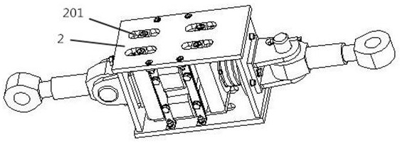
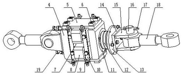
[0026] Embodiment 1, as figure 1 , figure 2 and image 3 As shown, this embodiment discloses a high-efficiency fast electric permanent magnet brake, which includes a frame, a mover assembly, a stator assembly, a spring assembly, a first output assembly, and a second output assembly;
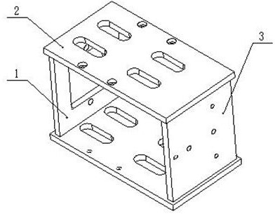
[0027] The structure of the rack is as figure 2 As shown: it includes a left side plate 1, a bottom plate 2, and a right side plate 3. There are two bottom plates 2, which are respectively arranged at the upper and lower ends of the left side plate 1 and the right side plate 3; The bolt through hole, the installation hole is convenient for installing the first output component, and the adjusting bolt 19 is connected in the bolt through hole to adjust the position of the mover component;
[0028] The mover assembly includes two mover blocks 4, two mover fixing plates 5, and a slider 6. The two mover blocks 4 are symmetrically arranged left and right, and the mover fixing plates 5 are arranged...
Embodiment 2
[0033] Embodiment 2, as Figure 4 , Figure 5 and Figure 6 As shown, this embodiment discloses a high-efficiency fast electric permanent magnet brake, which includes a frame, a mover assembly, a stator assembly, a spring assembly, a first output assembly, and a second output assembly;
[0034] The structure of the rack is as Figure 5 As shown: it includes a cylinder wall 1, a slide rail 2, and a support plate 3; the cylinder wall 1 is cylindrical, and two slide rails 2 are symmetrically arranged on the inner wall of the cylinder wall 1, and the support plate 3 is fixed on one end of the cylinder wall 1 .
[0035]The mover assembly includes two mover blocks 4, two mover fixing plates 5, and slideways 6. The two mover blocks 4 are symmetrically arranged left and right, and the mover fixing plates 5 are arranged at the upper and lower ends of the mover block 4 for The position of the mover block 4 is fixed, so that the distance between the two mover blocks 4 is constant.
...
PUM
 Abstract
Description
Claims
Application Information
 - Generate Ideas
- Intellectual Property
- Life Sciences
- Materials
- Tech Scout
- Unparalleled Data Quality
- Higher Quality Content
- 60% Fewer Hallucinations
Browse by: Latest US Patents, China's latest patents, Technical Efficacy Thesaurus, Application Domain, Technology Topic, Popular Technical Reports.
© 2025 PatSnap. All rights reserved.Legal|Privacy policy|Modern Slavery Act Transparency Statement|Sitemap|About US| Contact US: help@patsnap.com