
Power supply module unit of modular direct-current power supply system

A DC power supply system and power module technology, applied in the direction of electrical components, power electronics modification, output power conversion device, etc., can solve the problem that the stability of the fixed structure cannot be guaranteed, the heat dissipation effect of the unfavorable power module, and the buckle structure is complex and other problems, to achieve the effect of sliding structure avoidance, avoidance of blocking, and improvement of stability

Pending Publication Date: 2021-11-23
上海唐宣机电设备有限公司
View PDF1 Cites 0 Cited by
  • Summary
  • Abstract
  • Description
  • Claims
  • Application Information

AI Technical Summary

Problems solved by technology

[0003] The Chinese patent discloses a power module unit of a modular DC power supply system (authorized announcement number CN202178929U). This patented technology can realize rapid disassembly and assembly. The stability of the module cannot be guaranteed, and the structure of the buckle structure is relatively complicated, which is prone to mechanical failure. Generally, after the power module is assembled, the heat dissipation effect of a single module will be affected, and the installation structure will be more concentrated, which is not conducive to the heat dissipation effect of the power module.

Method used


Image

  • Power supply module unit of modular direct-current power supply system
  • Power supply module unit of modular direct-current power supply system
  • Power supply module unit of modular direct-current power supply system

Examples


Embodiment Construction

[0020] The following will clearly and completely describe the technical solutions in the embodiments of the present invention with reference to the accompanying drawings in the embodiments of the present invention. Obviously, the described embodiments are only some, not all, embodiments of the present invention. Based on the embodiments of the present invention, all other embodiments obtained by persons of ordinary skill in the art without making creative efforts belong to the protection scope of the present invention.

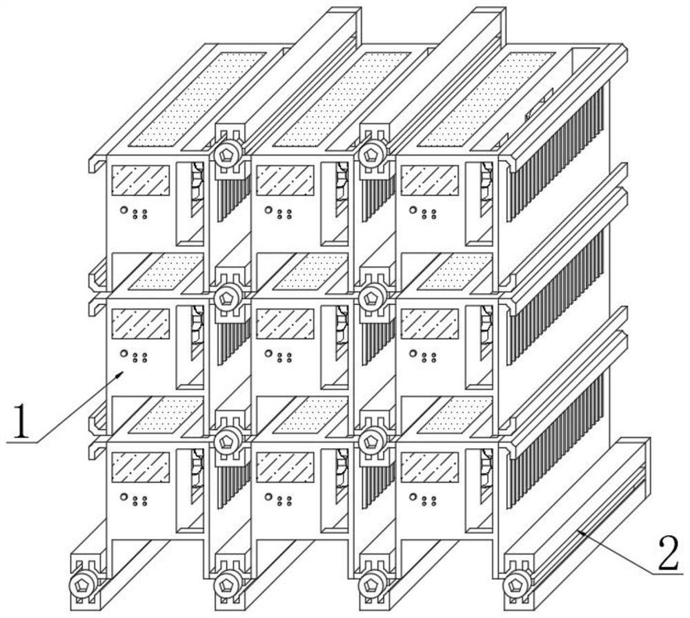
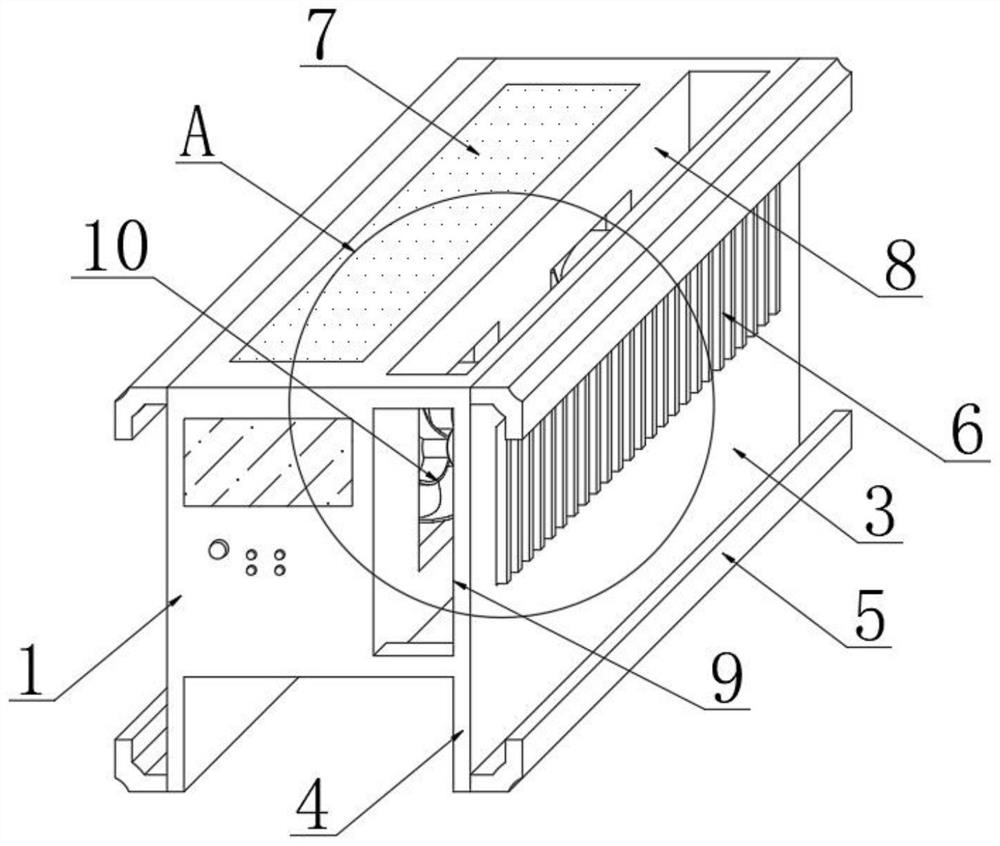
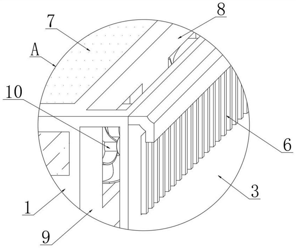
[0021] see Figure 1~5 , in an embodiment of the present invention, a power module unit of a modular DC power supply system includes a power module main body 1, a power module assembly member 2 is installed on the outside of the power module main body 1, and a lift is provided on the lower side of the power module main body 1. High feet 4, one side of the power module main body 1 is provided with a partition plate 3, one side of the partition plate 3 is instal...


PUM


Abstract

The invention relates to the technical field of power supply modules, in particular to a power supply module unit of a modular direct-current power supply system. The power supply module unit comprises a power supply module main body, a power supply module assembling component is arranged at the outer side of the power supply module main body, and a lower lifting foot is arranged at the lower side of the power supply module main body; a spacing board is arranged at one side of the power supply module main body, a heat exchange plate is installed at one side of the partition plate, and first heat dissipation openings are formed in the positions, close to the partition plate, of the upper side and the lower side of the power module body; second heat dissipation openings are formed in the positions, close to the partition plate, of the front side and the rear side of the power module body, and a fan is installed at one side of the power module main body. According to the invention, a sliding type assembly structure is arranged and is locked through screws after installation, the structure of a single power supply module is improved, the distance between two power supply modules adjacent to each other left and right is dispersed after assembly, and the heat discharge ports of the two power supply modules adjacent to each other up and down are communicated.

Description

technical field [0001] The invention relates to the technical field of power supply modules, in particular to a power supply module unit of a modular DC power supply system. Background technique [0002] The power module is a power supply that can be directly mounted on the printed circuit board. It is more common in the electric control room. It mainly plays the role of power supply control and increases the controllability of the circuit. Processors, microprocessors, memory, field programmable gate arrays, and other digital or analog loads. [0003] The Chinese patent discloses a power module unit of a modular DC power supply system (authorized announcement number CN202178929U). This patented technology can realize rapid disassembly and assembly. The stability of the power module cannot be guaranteed, and the structure of the buckle structure is relatively complicated, which is prone to mechanical failure. Generally, after the power module is assembled, the heat dissipati...

Claims


Application Information

Patent Timeline
IPC IPC(8): H02M1/00H05K5/02H05K7/20
CPCH02M1/00H05K5/0213H05K7/20909
Inventor 汪必军胡可邱亚明
Owner 上海唐宣机电设备有限公司
Learn More