Rotatable multifunctional unmanned aerial vehicle empennage
A kind of unmanned aerial vehicle, multi-functional technology, applied in the field of unmanned aerial vehicles, can solve the problems of tail bumping, damage, large space occupied by the tail, etc., to reduce the possibility of damage, simple installation steps, and easy transportation Effect
- Summary
- Abstract
- Description
- Claims
- Application Information
AI Technical Summary
Problems solved by technology
Method used
Image

Examples
Embodiment 1
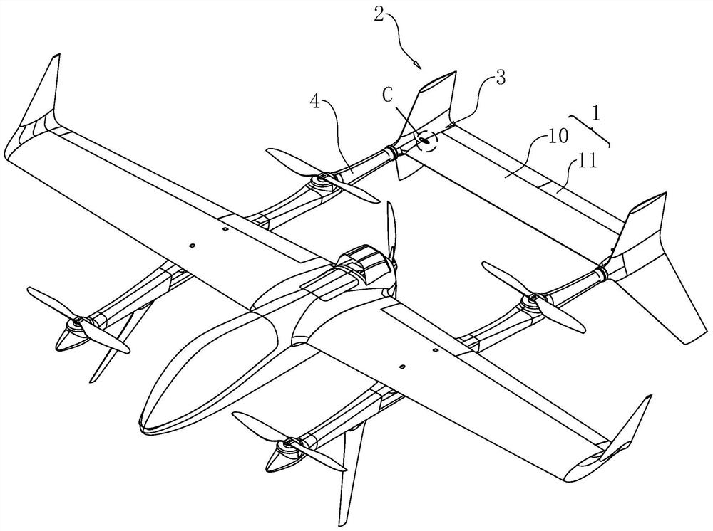
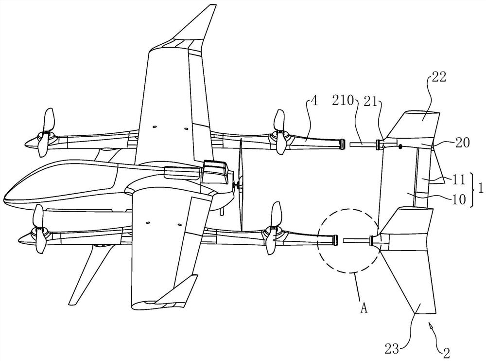
[0047] refer to figure 1 and figure 2 , a rotatable multifunctional UAV tail, which can be detachably arranged on the tail of the UAV. A rotatable multifunctional unmanned aerial vehicle tail, comprising a horizontal tail 1, a side wing 2 is respectively hinged at both ends of the horizontal tail 1, and a fixing part 3 for restricting the rotation of the side wing 2 is respectively arranged at both ends of the horizontal tail 1 .
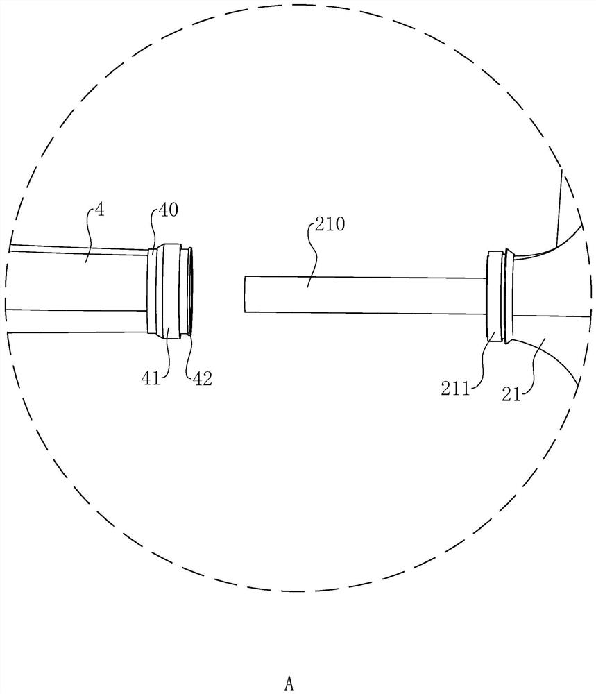
[0048] refer to figure 2 and image 3 , the UAV includes a fuselage and two installation rods 4 fixed on both sides of the fuselage, the two installation rods 4 are arranged in parallel, and the length direction of the installation rod 4 is parallel to the length direction of the fuselage. The side wing 2 includes a connecting portion 20, a mounting portion 21 is provided at the end of the connecting portion 20 close to the mounting rod 4, and an insertion rod 210 is fixedly connected to the mounting portion 21, the length direction of the ins...
Embodiment 2
[0058] refer to Figure 7 with Figure 8 The difference between this embodiment and Embodiment 1 is that, in this embodiment, the hinge 204 and the fixing member 3 are not provided between the horizontal stabilizer 1 and the side wing 2 . A rotating shaft 205 is fixedly connected to the two second installation platforms 203 of the connecting portion 20 , and the longitudinal direction of the rotating shaft 205 is parallel to the longitudinal direction of the insertion rod 210 . A supporting block 1000 is fixedly connected to the first installation platform 100 , and the rotating shaft 205 is rotated through the supporting block 1000 , and the wing 2 is hinged to the horizontal stabilizer 1 through the rotating shaft 205 . A first gear 206 is sleeved and fixed on the rotating shaft 205 .
[0059] refer to Figure 9 with Figure 10 , a driver 5 for driving the rotation shaft 205 is installed at both ends of the horizontal stabilizer 10, the driver 5 is a servo motor, the out...
PUM
 Abstract
Description
Claims
Application Information
 - R&D Engineer
- R&D Manager
- IP Professional
- Industry Leading Data Capabilities
- Powerful AI technology
- Patent DNA Extraction
Browse by: Latest US Patents, China's latest patents, Technical Efficacy Thesaurus, Application Domain, Technology Topic.
© 2024 PatSnap. All rights reserved.Legal|Privacy policy|Modern Slavery Act Transparency Statement|Sitemap