An oil pipeline traction and transfer device with anti-extrusion function
A technology for oil pipelines and transfer devices, which is applied in the direction of track systems, transportation and packaging, and load-hanging components. The effect of stability
- Summary
- Abstract
- Description
- Claims
- Application Information
AI Technical Summary
Problems solved by technology
Method used
Image
Examples
Embodiment 1
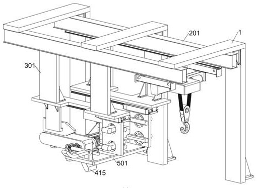
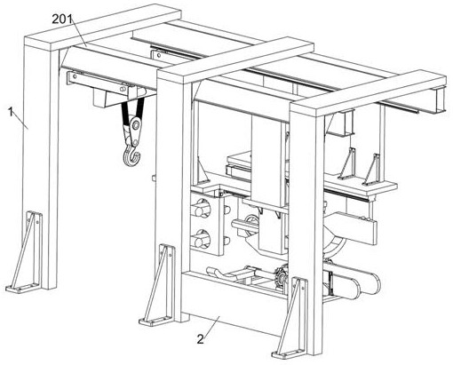
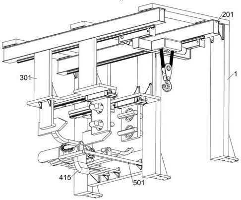
[0033] An oil pipeline traction and transfer device with anti-extrusion function, such as Figure 1-3 As shown, it includes a support frame 1, a fixed plate 2, a traction system and a positive swing system; there are three support frames 1, and the inner walls of two adjacent support frames 1 are welded with a fixed plate 2; the bottom of the three support frames 1 There is a traction system connected between them; the bottom of the traction system is connected with a positive swing system.
[0034] When the oil pipeline traction transfer device with anti-extrusion function is used, the oil pipeline traction transfer device with anti-extrusion function is installed on the ship through the support frame 1 and the fixed plate 2, and the oil pipeline to be docked is firstly equipped with external traction equipment Towed to the side of the ship, the worker hangs the load-bearing sling of the oil pipeline in the traction system, and pulls the oil pipeline to the docking position t...
Embodiment 2
[0040] On the basis of Example 1, such as figure 1 and Figure 8-12 As shown, it also includes an upper roof system; the left part of the front side wall of the fixed plate 2 is connected with an upper roof system; the upper roof system includes a first support rod 401, a bearing plate 402, a second support rod 403, and a first cross bar 404 , the first limit slide rail 405, the first limit slide plate 406, the tooth plate 407, the wedge block 408, the linkage block 409, the second limit slide plate 410, the second limit slide rail 411, the first shaft 412, The flat gear 413, the upper top plate 414 and the first bevel gear 415; the fixed plate 2 is welded with the first support rod 401 on the side below the first mounting bracket 201; the upper surface of the first support rod 401 is welded with two bearing plates 402; The front side wall of the plate 2 is welded with a second support bar 403; the second support bar 403 is located on the side of the first support bar 401; th...
PUM
 Abstract
Description
Claims
Application Information
 - R&D
- Intellectual Property
- Life Sciences
- Materials
- Tech Scout
- Unparalleled Data Quality
- Higher Quality Content
- 60% Fewer Hallucinations
Browse by: Latest US Patents, China's latest patents, Technical Efficacy Thesaurus, Application Domain, Technology Topic, Popular Technical Reports.
© 2025 PatSnap. All rights reserved.Legal|Privacy policy|Modern Slavery Act Transparency Statement|Sitemap|About US| Contact US: help@patsnap.com


