Safety fence for maintenance of power transformation box

A technology for safety fences and substations, applied in fences, building types, buildings, etc., can solve the problems of wasting transportation resources and storage resources, save transportation resources and storage resources, reduce the probability of corrosion, and save costs.

Pending Publication Date: 2021-11-26
SHANGHE COUNTY POWER SUPPLY CO STATE GRID SHANDONG ELECTRIC POWER CO +1
View PDF9 Cites 0 Cited by
  • Summary
  • Abstract
  • Description
  • Claims
  • Application Information

AI Technical Summary

Problems solved by technology

[0004] Through the above operations, it can be seen that when the transformer box is inspected and maintained each time, it is necessary to use vehicle transport railings and store railings on the ground, so transportation resources and storage resources are wasted

Method used


Image

  • Safety fence for maintenance of power transformation box
  • Safety fence for maintenance of power transformation box
  • Safety fence for maintenance of power transformation box

Examples


Embodiment 1

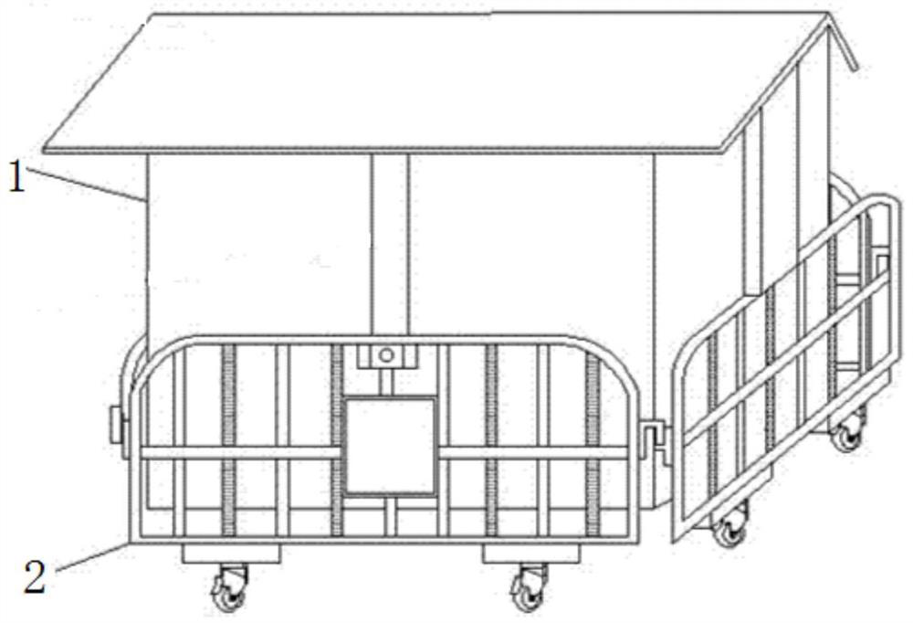
[0050] Such as Figure 2-8 As shown, a safety fence for transformer box maintenance includes a railing 2 .

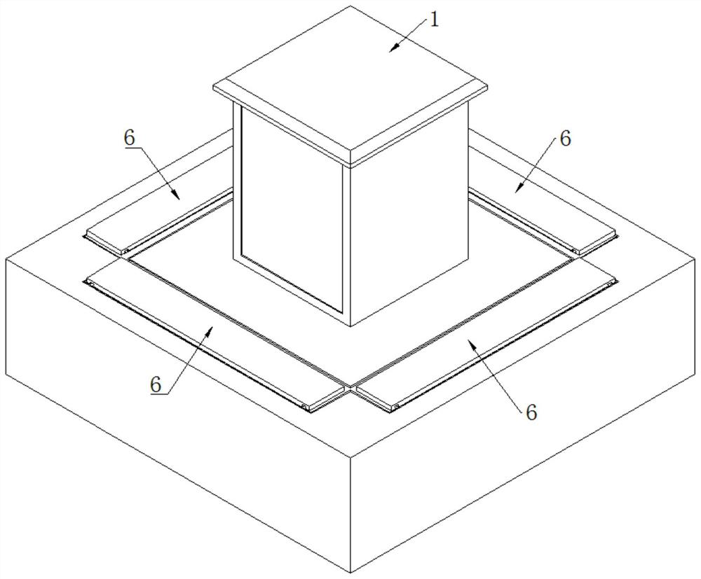
[0051] A reserved pit 3 is arranged in the land around the transformer box 1, and the reserved pit 3 adopts a reinforced concrete pit body structure. The railing 2 is set in the reserved pit 3 . The pit wall of reserved pit 3 is provided with railing guide rail 31, and railing rail 31 is vertically arranged, and railing guide rail 31 is fixed on the pit wall of reserved pit 3 by screw, and railing 2 is provided with railing guide groove 21, and railing guide rail 31 is inserted in railing Inside the guide groove 21. When the railing 2 moves vertically up and down in the reserved pit 3 , the railing guide rail 31 and the railing guide slot 21 move relatively.

[0052] A driving assembly 4 is arranged in the reserved pit 3, and the driving assembly 4 is used to drive the railing 2 so that the railing 2 can move up and down in the reserved pit 3 along the vertical direc...

Embodiment 2

[0064] Such as Figure 9-15 Shown, present embodiment 2 makes further improvement on the basis of embodiment 1:

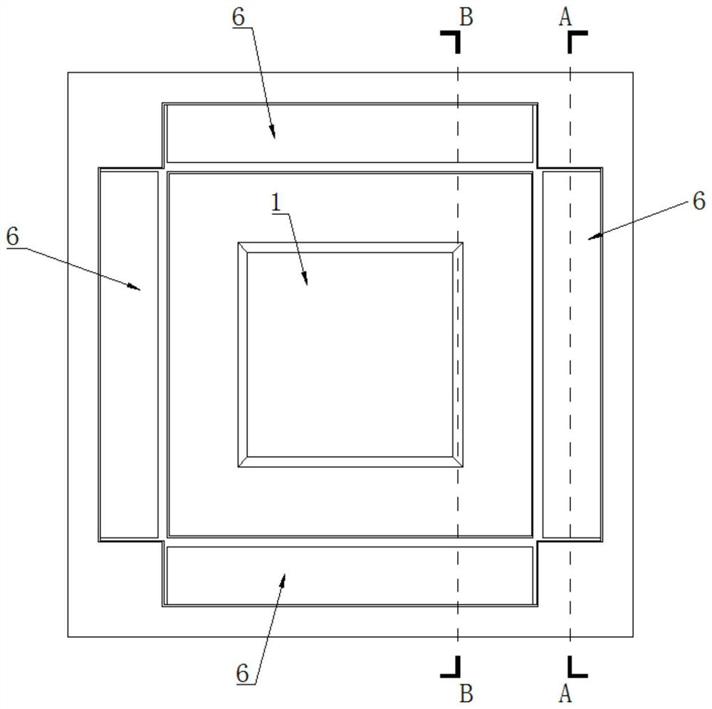
[0065] In the safety fence for transformer box maintenance in the second embodiment, the opening of the reserved pit 3 is provided with a pit mouth sealing strip 34 , and the pit mouth sealing strip 34 is fixed to the pit mouth of the reserved pit 3 by screws. By arranging the pit mouth sealing strip 34, the rainwater on the ground can be prevented from entering the reserved pit 3 from the gap between the cover plate 6 and the pit mouth of the reserved pit 3, thereby reducing the corrosion of the railing 2 in the reserved pit 3 due to wet rainwater chance, which is beneficial to prolong the service life of the railing 2, thereby saving the cost of replacing and maintaining the railing 2.

[0066] Further, the upper end surface of the cover plate 6 is provided with a mounting groove 62, and turf (not shown in the figure) is laid in the mounting groove 62 . In this...


PUM


Abstract

The invention discloses a safety fence for maintenance of a power transformation box, and relates to the technical field of safety protection equipment of power transformation boxes. The safety fence comprises a handrail, the handrail is arranged in a reserved pit of the land around the power transformation box, a driving assembly used for driving the handrail to vertically slide along the pit wall of the reserved pit is arranged in the reserved pit, and a horizontally-arranged supporting rod is arranged at a pit opening of the reserved pit; and the supporting rod is vertically and slidably connected with the pit wall of the reserved pit, the supporting rod is provided with a cover plate used for shielding the pit opening of the reserved pit, the cover plate is horizontally and slidably connected with the supporting rod, an inclined rod is arranged above the handrail, the lower end of the inclined rod is hinged to the pit wall of the reserved pit, the upper end of the inclined rod is hinged to one end of the cover plate, and an elastic piece used for pushing the inclined rod to the handrail is arranged on the wall of the reserved pit. Transportation resources and storage resources can be saved.

Description

technical field [0001] The invention relates to the technical field of safety protection equipment for transformer boxes, in particular to a safety fence for transformer box maintenance. Background technique [0002] A transformer box is a device that transforms, concentrates, and distributes voltage and current in a power system. Most of the substations are built in green belts to keep away from passers-by on the road. In order for the transformer box to operate normally, it is necessary for the staff to regularly check and maintain the transformer box. When overhauling and maintaining the transformer box, it is necessary to temporarily build a safety fence around the transformer box to prevent passers-by from getting in and being injured by electricity. [0003] Such as figure 1 As shown, the existing safety fence includes a railing 2 . When setting up the safety fence, the staff needs to use the vehicle to transport the railing 2 to the site, and then the staff surrou...

Claims


Application Information

Patent Timeline
Patent Type & Authority Applications(China)
IPC IPC(8): E04H17/00
CPCE04H17/009
Inventor 李健郑伟然黄庆博郭际明王辉王春华
Owner SHANGHE COUNTY POWER SUPPLY CO STATE GRID SHANDONG ELECTRIC POWER CO
Why Eureka
Try Eureka