
IPv6 remote monitoring device and method

A remote monitoring device and remote monitoring technology, applied in the direction of data exchange through path configuration, closed-circuit television system, electrical components, etc., can solve the problems of complex configuration, inconvenient popularization, and inconsistent communication standards, so as to ensure safety and Effects of privacy, improved convenience and speed, and simple architecture

Inactive Publication Date: 2007-02-28
BEIJING INTERNET INST
View PDF0 Cites 17 Cited by
  • Summary
  • Abstract
  • Description
  • Claims
  • Application Information

AI Technical Summary

Problems solved by technology

Due to the flaws in the design of the IPv4 protocol, IPv4 addresses are almost exhausted, and its address resources are far from meeting the needs of global terminal equipment growth
In a large-scale monitoring network, the number of terminal monitoring devices may reach tens of thousands, and each terminal needs to have its own IP address, which cannot be supported by the existing IPv4 network, and the IPv4 network cannot guarantee Scalability and enabling end-to-end access
In addition, when so many monitoring devices are deployed in an IPv4 network environment, the IP addresses and gateways of each camera terminal need to be manually configured, and the labor intensity and speed cannot meet the operation requirements of a large-scale monitoring network.
[0005] To sum up, there are many limitations in the existing video surveillance devices: 1) Due to the emergence of the public operator-level video surveillance system, the number of surveillance devices on the network has increased sharply, and the existing IPv4 technology cannot allocate The unique IP address in the world, so that the monitoring device can be accessed anytime and anywhere on the Internet
2) The configuration is complex and cannot adapt to the operation requirements of large-scale monitoring networks
3) Security cannot be guaranteed in the public operation level video surveillance system
4) The communication standards are not uniform, and the interconnection and intercommunication between various devices cannot be realized
5) Complicated to use, poor ease of use, and not easy to popularize
6) Mobility cannot be guaranteed

Method used


Image

  • IPv6 remote monitoring device and method
  • IPv6 remote monitoring device and method
  • IPv6 remote monitoring device and method

Examples


Embodiment Construction

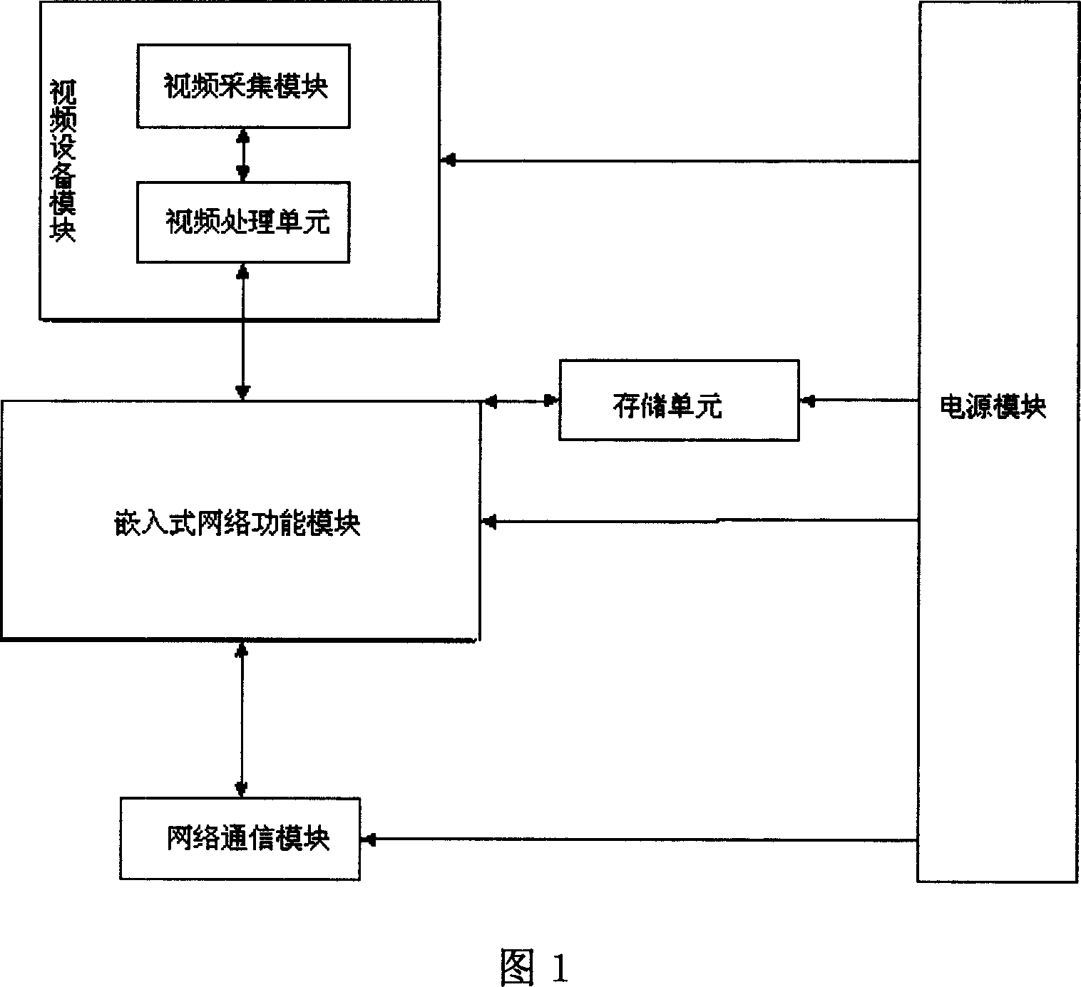
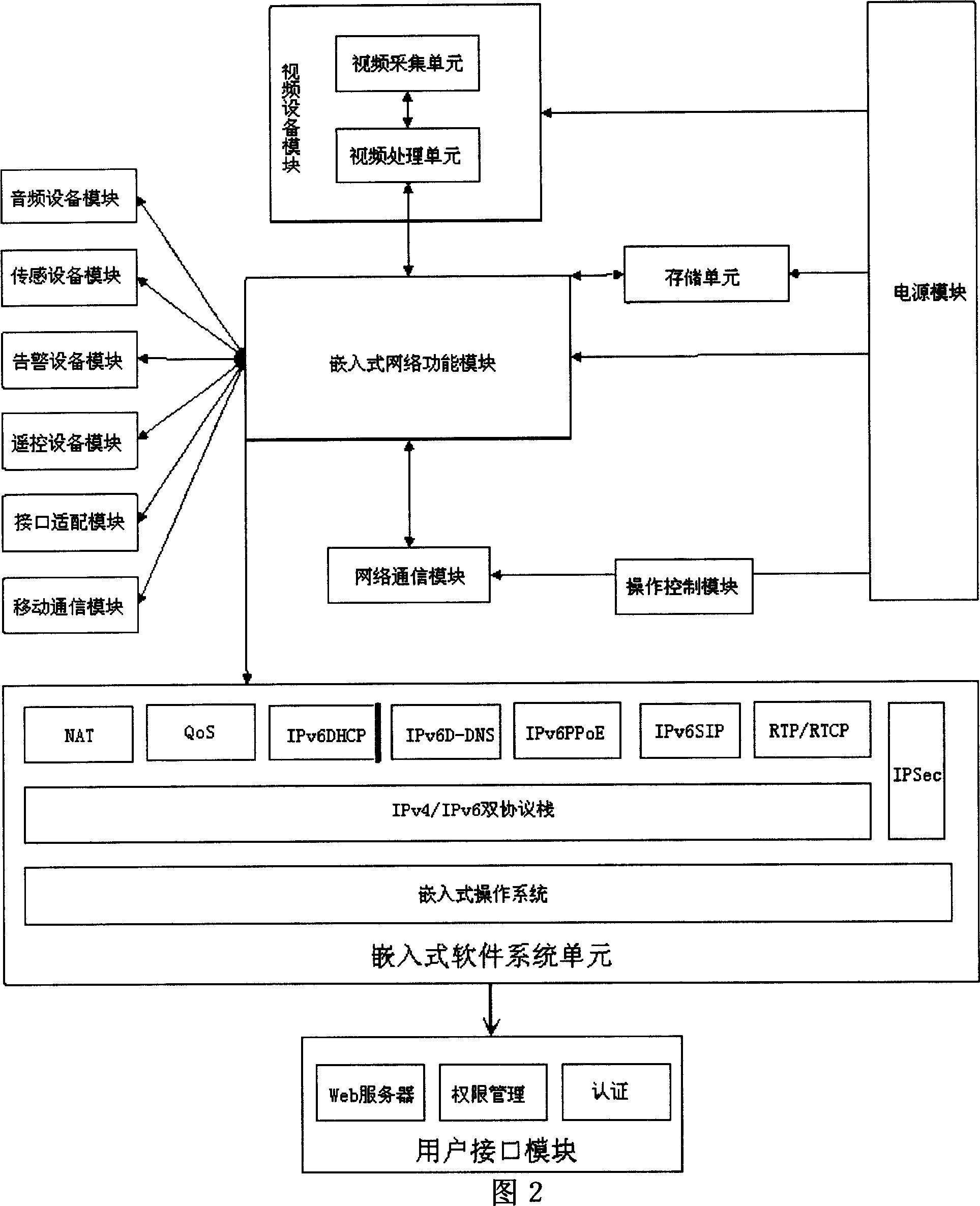
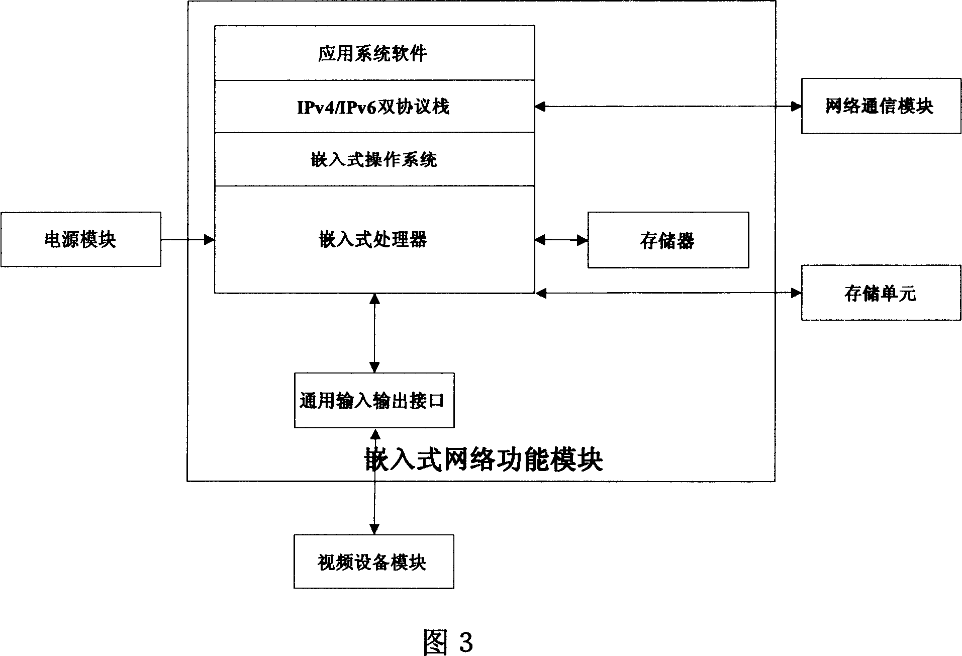
[0054] As shown in Figure 1, it is a schematic diagram of the system composition of the IPv6 remote monitoring device of the present invention, the IPv6 remote monitoring device is connected with the monitoring center and the remote monitoring client through a communication network, and it includes:

[0055] The network communication module is used for data communication with the monitoring center, sending monitoring information and receiving control information of the monitoring center through the network, which supports the IPv6 protocol, and the network communication module sends the received identity verification information to the embedded network function module The embedded network function module performs security verification according to the setting information stored in the storage unit. After the security verification is passed, the embedded network function module controls the video equipment module to collect video according to the instructions of the network commu...


PUM


Abstract

The invention relates to an IPv6 remote detector and relative method. Wherein, it comprises network communication module, video module, embedded network module, and power module, while the embedded network module is connected other three modules to be integrated in one embedded system. The inventive device uses next-generation internet, supports IPv6 and / or IPv4 network protocols, etc, to transmit data, with network interface, while it can be connected to internet independently. And it has unique address and unique globe IP address. The invention can realize remote video, alarm and detection, etc.

Description

technical field [0001] The invention relates to an IPv6 remote monitoring device and a method thereof, belonging to the comprehensive technical field of communication, computer network management and video monitoring network. Background technique [0002] The development of video surveillance system has gone through three stages of analog, semi-digital and full-digital, and it has been widely used in many fields such as communication, finance, transportation, mining and so on at home and abroad, and plays a huge role. With the development of related technologies, large-scale operation-level video surveillance services that are globally accessible, open and interoperable, and standardized are becoming new development needs. However, due to the lack of industry standards and low market access requirements, some equipment manufacturers blindly produce all kinds of video surveillance equipment in pursuit of commercial interests, resulting in the reliability, stability, openness,...

Claims


Application Information

Patent Timeline
IPC IPC(8): H04L29/06H04L12/28H04N7/18
Inventor 华宁刘东陆乐董新久石宇光陈东
Owner BEIJING INTERNET INST
Learn More