

Piezometric tube connecting structure
A connection structure and pressure measuring tube technology, which is applied in the direction of measuring fluid pressure, measuring fluid pressure through mechanical components, measuring devices, etc. Experimental results, water leakage in the experimental bench and other problems, to achieve good fastening effect, prevent rotation, and good positioning effect
- Summary
- Abstract
- Description
- Claims
- Application Information
AI Technical Summary
Problems solved by technology
Method used
Image

Examples
Embodiment Construction
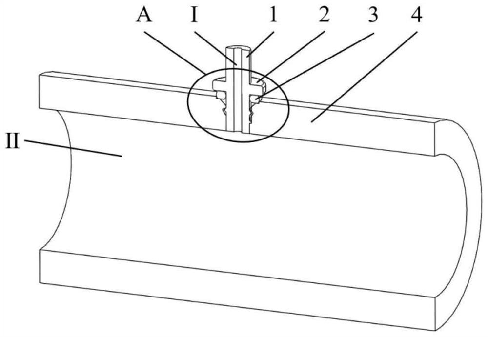
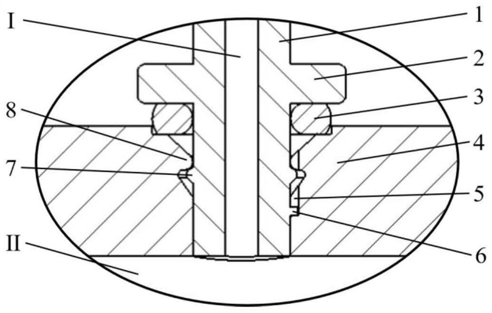
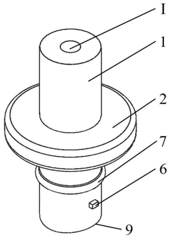
[0018] Below in conjunction with accompanying drawing, the present invention will be further described. Such as figure 1 , figure 2 As shown, a pressure measuring tube connection structure includes a fastening structure, a positioning structure and a sealing structure. The fastening structure includes a compression ring (2) on the lead-out end (1) of the pressure measuring tube, a small flange (7), a large flange (8) on the tube wall (4) to be measured, etc.; The positioning structure is composed of a positioning key (6) on the lead-out end (1) of the pressure measuring tube and a positioning groove (5) on the wall of the tube to be measured (4); the sealing structure is composed of an O-shaped rubber gasket (3) and the above-mentioned The fastening structure is jointly composed. When installing, nest the O-shaped rubber gasket (3) on the lower end of the pressure measuring tube lead-out end (1), and press the end with the small flange (7) into the hole processed on the tu...
PUM
 Abstract
Description
Claims
Application Information