Testing device for clutch booster of vehicle
A technology for testing devices and boosters, which is applied in the testing of machines/structural components, measuring devices, testing of mechanical components, etc. It can solve the problems of vehicle control failure, accidents, clutch failure, etc., to eliminate safety hazards and reduce manufacturing costs. Low, the effect of reducing accidents
- Summary
- Abstract
- Description
- Claims
- Application Information
AI Technical Summary
Problems solved by technology
Method used
Image
Examples
Embodiment 1
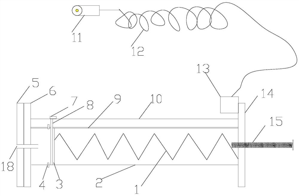
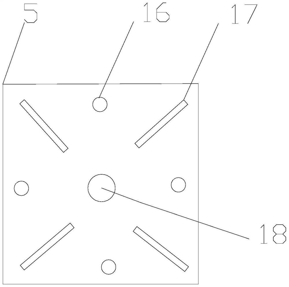
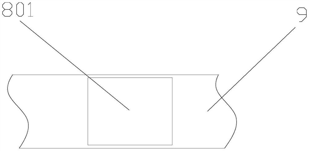
[0020] A test device for a vehicle clutch booster, as shown in the figure, includes a front connecting plate 6, a steel cylinder 2, a rear connecting plate 14, a movable bracket 8, a spring 1, a load cell 3 and a caliper display 7, and the front connecting plate 6 is connected by the steel cylinder 2 and the rear connecting plate 14, the steel cylinder 2 is provided with a bracket movable groove 9, the bracket movable groove 9 is provided with a movable bracket 8 that moves on the bracket movable groove 9, and the movable bracket 8 is provided with a caliper display 7. The movable support 8 is connected with the load cell 3, and the load cell 3 is connected with the rear connecting plate 14 through the spring 1. The stroke displacement data of the clutch booster push rod is tested through the caliper display 7, and the thrust of the clutch booster push rod is tested through the load cell 3, so that the clutch booster push rod can be tested on site through this simple test devic...
Embodiment 2
[0029] A test device for a vehicle clutch booster, as shown in the figure, includes a front connecting plate 6, a steel cylinder 2, a rear connecting plate 14, a movable bracket 8, a spring 1, a load cell 3 and a caliper display 7, and the front connecting plate 6 is connected by the steel cylinder 2 and the rear connecting plate 14, the steel cylinder 2 is provided with a bracket movable groove 9, the bracket movable groove 9 is provided with a movable bracket 8 that moves on the bracket movable groove 9, and the movable bracket 8 is provided with a caliper display 7. The movable support 8 is connected with the load cell 3, and the load cell 3 is connected with the rear connecting plate 14 through the spring 1. The stroke displacement data of the clutch booster push rod is tested through the caliper display 7, and the thrust of the clutch booster push rod is tested through the load cell 3, so that the clutch booster push rod can be tested on site through this simple test devic...
Embodiment 3
[0031] A test device for a vehicle clutch booster, as shown in the figure, includes a front connecting plate 6, a steel cylinder 2, a rear connecting plate 14, a movable bracket 8, a spring 1, a load cell 3 and a caliper display 7, and the front connecting plate 6 is connected by the steel cylinder 2 and the rear connecting plate 14, the steel cylinder 2 is provided with a bracket movable groove 9, the bracket movable groove 9 is provided with a movable bracket 8 that moves on the bracket movable groove 9, and the movable bracket 8 is provided with a caliper display 7. The movable support 8 is connected with the load cell 3, and the load cell 3 is connected with the rear connecting plate 14 through the spring 1. The stroke displacement data of the clutch booster push rod is tested through the caliper display 7, and the thrust of the clutch booster push rod is tested through the load cell 3, so that the clutch booster push rod can be tested on site through this simple test devic...
PUM
 Abstract
Description
Claims
Application Information
 - R&D
- Intellectual Property
- Life Sciences
- Materials
- Tech Scout
- Unparalleled Data Quality
- Higher Quality Content
- 60% Fewer Hallucinations
Browse by: Latest US Patents, China's latest patents, Technical Efficacy Thesaurus, Application Domain, Technology Topic, Popular Technical Reports.
© 2025 PatSnap. All rights reserved.Legal|Privacy policy|Modern Slavery Act Transparency Statement|Sitemap|About US| Contact US: help@patsnap.com


