Near-field local irradiation target scattering near-far field conversion method

A technology of target scattering and local irradiation, applied in radio wave measurement systems, instruments, etc., can solve problems such as imaging center alignment problems, and achieve flexible sampling methods

Pending Publication Date: 2021-11-26
SHANGHAI RADIO EQUIP RES INST
View PDF0 Cites 1 Cited by
  • Summary
  • Abstract
  • Description
  • Claims
  • Application Information

AI Technical Summary

Problems solved by technology

If the traditional method based on target near-field SAR/ISAR imaging is used to deal with the problem of local illumination in the near field, the target area needs to be segmented first, and then the far fie

Method used


Image

  • Near-field local irradiation target scattering near-far field conversion method
  • Near-field local irradiation target scattering near-far field conversion method
  • Near-field local irradiation target scattering near-far field conversion method

Examples


Embodiment 1

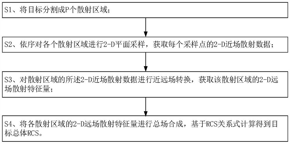
[0059] The present invention provides a near-field local irradiation target scattering near-far field conversion method, which is suitable for obtaining the overall RCS of the target under 2-D plane sampling, such as figure 1 As shown, the method comprises the steps of:

[0060] S1. Divide the target into P scattering regions;

[0061] S2. Perform 2-D plane sampling on each scattering area in sequence to obtain 2-D near-field scattering data of each sampling point;

[0062] Step S2 includes:

[0063] S21. Determine the sampling plane of the near-field scattering data in the scattering area;

[0064] S22. On the sampling plane, with the center of the sampling plane as the center, within the circle determined by the nearest radius and the farthest radius, use any antenna to sample at any position of the circle, and record the The antenna receives the voltage and the location of the sampling point.

[0065] S3. Based on the expression of the receiving voltage of the 2-D near-...

Embodiment 2

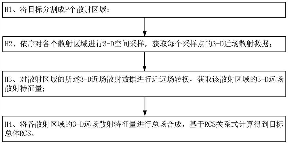
[0081] The present invention also provides a near-field local irradiation target scattering near-far field conversion method, which is suitable for obtaining the overall RCS of the target under 3-D space sampling, and the method includes steps:

[0082] H1. Divide the target into P scattering regions;

[0083] H2. Perform 3-D spatial sampling on each scattering area in sequence to obtain 3-D near-field scattering data of each sampling point;

[0084] Step H2 includes:

[0085] H21. Determine the sampling space of the near-field scattering data in the scattering area;

[0086] H22. In the sampling space, with the center of the sampling space as the center, in the spherical layer determined by the nearest radius and the farthest radius, use any antenna to sample at any position of the spherical layer, and record the value of each sampling point The antenna receives the voltage and the location of the sampling point.

[0087] H3. Based on the expression of the received voltage...


PUM


Abstract

The invention provides a near-field local irradiation target scattering near-far field conversion method. The method comprises the following steps: S1, segmenting a target into P scattering areas; s2, performing 2-D plane sampling on each scattering area in sequence to obtain 2-D near-field scattering data of each sampling point; s3, performing near-far field conversion on the 2-D near-field scattering data of the scattering area based on an expression of receiving voltage of a 2-D near-field test antenna, and obtaining a 2-D far-field scattering characteristic quantity of the scattering area; and S4, performing total field synthesis on the 2-D far field scattering characteristic quantity of each scattering region, and performing calculation based on an RCS relational expression to obtain a target total RCS. The invention further provides a near-field local irradiation target scattering near-far field conversion method which is suitable for obtaining the total RCS of the target under 3-D space sampling.

Description

technical field [0001] The invention relates to the technical field of electromagnetic scattering and inverse scattering, in particular to a near-field local irradiation target scattering near-far field conversion method. Background technique [0002] In recent years, the RCS (Radar Cross section) near-field test technology, which has been actively developed in recent years, refers to a test in the near-field that does not meet the far-field conditions, and then a combination of test and calculation to obtain the target RCS through near-far field conversion. technology. When the electrical size of the target is large, the far-field conditions become extremely harsh and difficult to achieve in the experimental field. The near-field test only needs to be carried out in a limited experimental field with several times the target size, which is cheap and convenient. However, the near-field test needs to perform near-far field conversion processing on the test data to obtain the...

Claims


Application Information

Patent Timeline
IPC IPC(8): G01S7/41
CPCG01S7/41
Inventor 贺新毅童广德徐秀丽廖意
Owner SHANGHAI RADIO EQUIP RES INST
Why Eureka
Try Eureka