Information processing device
A technology of information processing devices and control devices, which is applied in the direction of electrical digital data processing, instruments, calculations, etc., to achieve the effect of suppressing memory conflicts and preventing memory conflicts
- Summary
- Abstract
- Description
- Claims
- Application Information
AI Technical Summary
Problems solved by technology
Method used
Image
Examples
Embodiment approach 1
[0026] Hereinafter, an embodiment (hereinafter also referred to as "the present embodiment") of one aspect of the present invention will be described based on the drawings.
[0027] §1 Application example
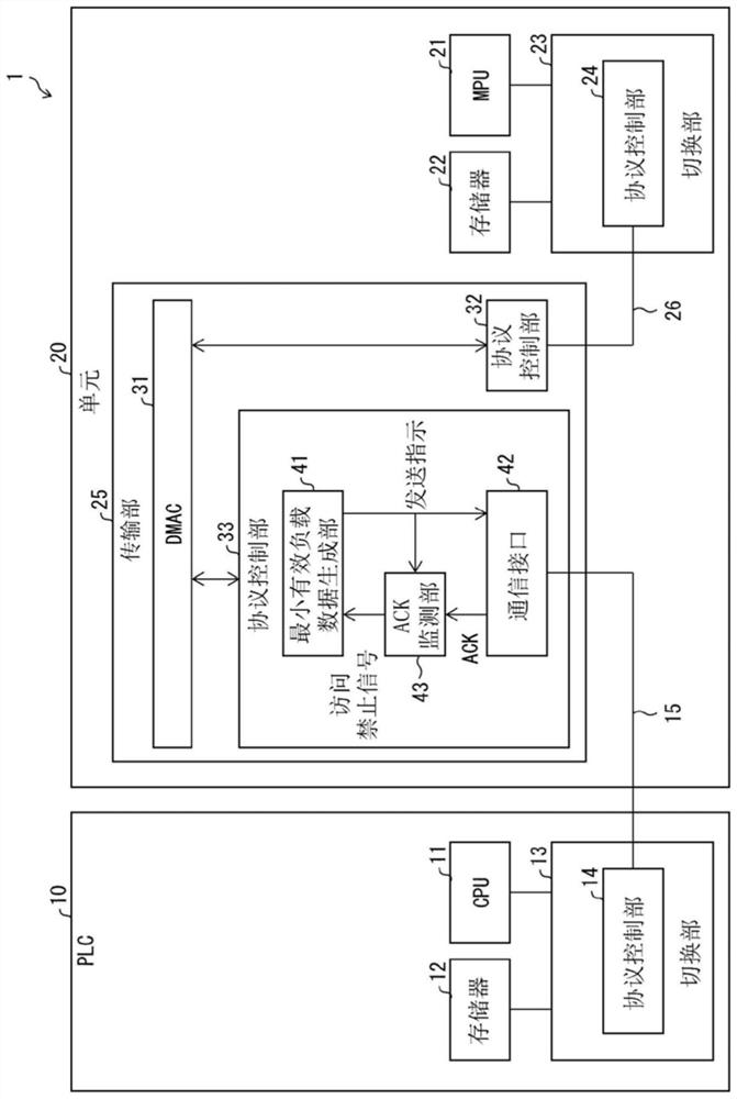
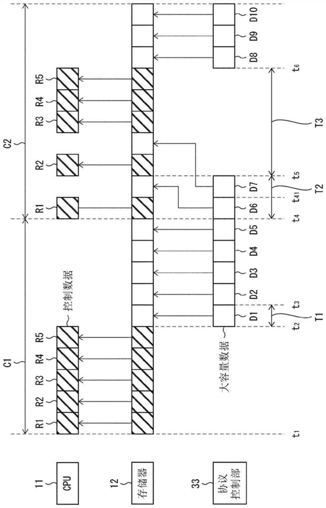
[0028] First, refer to figure 1 and 2 to describe an example of a scene to which the present invention is applied. like figure 1 As shown, the unit 20 of the present embodiment is an information processing device which is connected to a programmable logic controller (PLC) 10 in the control system 1 and operates in cooperation with the PLC 10 . The protocol control unit 33 in the unit 20 shares the memory 12 in the PLC 10 with the CPU 11 in the PLC 10 , and both communicate with the memory 12 via the serial bus 15 . That is, the CPU 11 and the protocol control unit 33 share the memory 12 . In the control system 1 , a configuration for preventing memory conflicts between the CPU 11 and the protocol control unit 33 is introduced.
[0029] like figure 2 As shown, when a ...
Embodiment approach 2
[0078] Hereinafter, an embodiment (hereinafter also referred to as "the present embodiment") of another aspect of the present invention will be described based on the drawings.
[0079] §2 Structure example
[0080] (Configuration of Control System 1A)
[0081] Image 6 It is a block diagram which shows the structure of the main part of the control system 1A of this embodiment. In the example in this figure, the control system 1 includes a PLC 10 , a unit 20 , and a setting device 50 . Image 6 The internal structures of PLC10 and unit 20 are respectively figure 1 The internal structures of the PLC 10 and the unit 20 are the same, so the detailed description will not be repeated.
[0082] The setting device 50 is an external device connected to the PLC 10 and operated by a user such as an administrator of the control system 1 . The setting device 50 includes a program creation unit 51 , a simulation execution unit 52 , and a setting unit 53 . The setting unit 53 is conne...
PUM
 Abstract
Description
Claims
Application Information
 - R&D
- Intellectual Property
- Life Sciences
- Materials
- Tech Scout
- Unparalleled Data Quality
- Higher Quality Content
- 60% Fewer Hallucinations
Browse by: Latest US Patents, China's latest patents, Technical Efficacy Thesaurus, Application Domain, Technology Topic, Popular Technical Reports.
© 2025 PatSnap. All rights reserved.Legal|Privacy policy|Modern Slavery Act Transparency Statement|Sitemap|About US| Contact US: help@patsnap.com


