
Electric single-beam crane for annular track

A technology of ring track and crane, which is applied in the direction of track system, walking mechanism, load block, etc., can solve the problems of insufficient stability of ring track, low efficiency of cargo handling, and influence on the use effect, so as to improve the transportation efficiency of the device and improve the hook lifting efficiency. range, the effect of enhancing the effect of use

Pending Publication Date: 2021-11-30
合肥汇强起重机械有限公司
View PDF0 Cites 0 Cited by
  • Summary
  • Abstract
  • Description
  • Claims
  • Application Information

AI Technical Summary

Problems solved by technology

1. Most of the existing electric single-girder cranes run on I-steel rails, which leads to the fact that when the electric single-girder crane needs to turn, it can only go straight in a straight line. At the same time, when the hook puts down the goods, because the goods are heavy, the sling will fall quickly, which is easy to damage the goods; 2. When the existing electric single-girder crane uses a single electric hoist to carry the heavy goods, the goods handling efficiency is low , when multiple electric hoists work at the same time, it is inevitable that there will be bumps, which will affect their use effect; 3. The circular track of the existing electric single-girder crane is insufficient due to the back and forth operation of the crane; therefore, we propose a Electric single girder crane for circular track

Method used


Image

  • Electric single-beam crane for annular track
  • Electric single-beam crane for annular track
  • Electric single-beam crane for annular track

Examples


Embodiment Construction

[0027] In order to make the technical means, creative features, goals and effects achieved by the present invention easy to understand, the present invention will be further described below in conjunction with specific embodiments.

[0028] In the description of the present invention, it should be noted that the terms "upper", "lower", "inner", "outer", "front end", "rear end", "both ends", "one end", "another end" The orientation or positional relationship indicated by etc. is based on the orientation or positional relationship shown in the drawings, and is only for the convenience of describing the present invention and simplifying the description, rather than indicating or implying that the referred device or element must have a specific orientation, use a specific Azimuth configuration and operation, therefore, should not be construed as limiting the invention. In addition, the terms "first" and "second" are used for descriptive purposes only, and should not be understood ...


PUM


Abstract

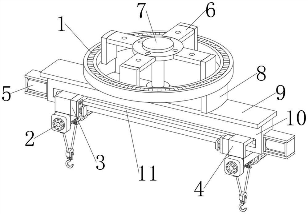
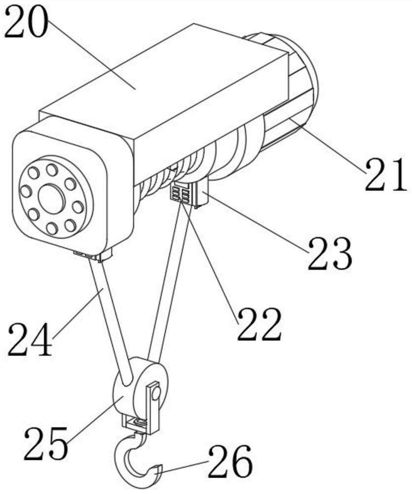
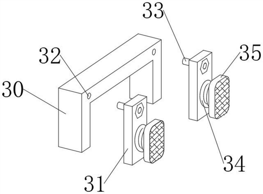
The invention discloses an electric single-beam crane for an annular track. The electric single-beam crane comprises the annular track, the front end inner wall, the left end inner wall, the rear end inner wall and the right end inner wall of the annular track are jointly and fixedly provided with an installation fixing device, and the left portion and the right portion of the lower end of the annular track are each movably provided with two track connecting sliding blocks; a connecting supporting plate is fixedly installed at the lower ends of the two track connecting sliding blocks jointly, a supporting device is fixedly installed between the connecting supporting plate and the installation fixing device, a connecting frame is fixedly installed at the lower end of the connecting supporting plate, and sliding grooves are formed in the inner wall of the upper end and the inner wall of the lower end of the connecting frame. According to the electric single-beam crane for the annular track, the crane can be rapidly and conveniently steered through a pushing device, a sliding device and a lifting conveying device, the hooking range of the crane is widened, the using effect of an electric hoist is improved through an anti-collision device. The stability of the annular track is improved by the installation fixing device and the supporting device.

Description

technical field [0001] The invention relates to the technical field of cranes, in particular to an electric single-girder crane for a ring track. Background technique [0002] A crane refers to a multi-action hoisting machine that lifts vertically and carries heavy objects horizontally within a certain range. Electric single-girder crane is a kind of light and small lifting equipment. It runs on the I-beam track. It can be divided into electric and manual. The heavy objects are hung on it. It is relatively simple and has many applications. It is used more and more widely. 1. Most of the existing electric single-girder cranes run on I-steel rails, which leads to the fact that when the electric single-girder crane needs to turn, it can only go straight in a straight line. At the same time, when the hook puts down the goods, because the goods are heavy, the sling will fall quickly, which is easy to damage the goods; 2. When the existing electric single-girder crane uses a sin...

Claims


Application Information

Patent Timeline
IPC IPC(8): B66C11/00B66C9/14B66D1/12B66D1/30B66C7/08
Inventor 邹磊
Owner 合肥汇强起重机械有限公司
Learn More