

Concrete vibrating device for building
A vibrating device and concrete technology, applied in construction, building structure, construction material processing and other directions, can solve the problem of not being able to discharge all the air cleanly, and achieve the effect of eliminating air bubbles, improving service life and improving efficiency.
- Summary
- Abstract
- Description
- Claims
- Application Information
AI Technical Summary
Problems solved by technology
Method used
Image

Examples
Embodiment 1
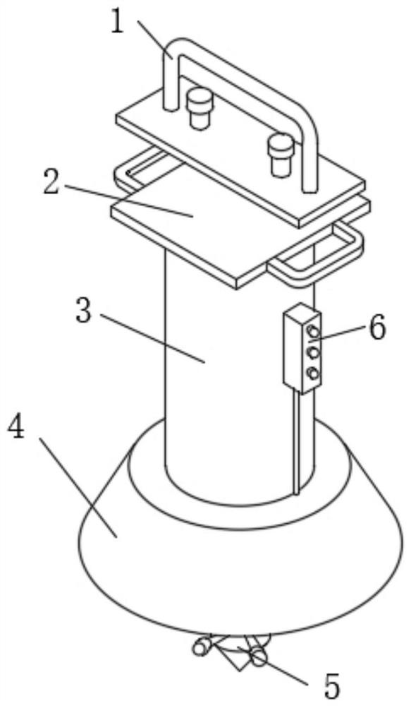
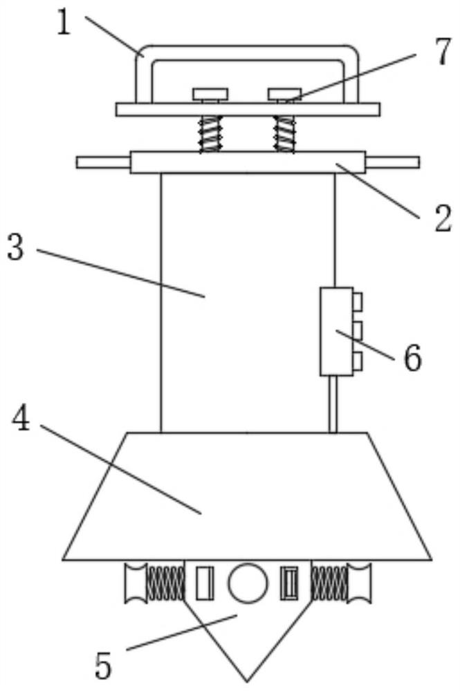
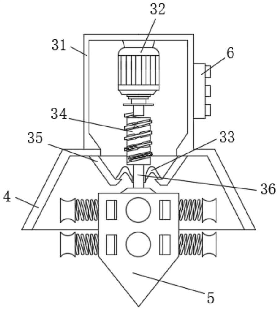
[0033] Such as Figure 1-4 As shown, the present invention provides a technical solution: a concrete vibrating device for construction, comprising a hand handle bar 1, both sides of the bottom of the hand handle bar 1 are sleeved with cushioning bolts 7, and the cushioning bolts 7 The bottom end of the shock bolt 7 is fixedly connected with a horizontal plate 2, the bottom of the horizontal plate 2 is fixedly connected with a motor barrel 3, and the surface on the right side of the motor barrel 3 is fixedly connected with a control switch 6. The bottom is fixedly connected with a protective cover 4, the inner cavity of the protective cover 4 is provided with a vibrating device 5, the motor barrel 3 includes a barrel wall 31, and the middle of the inner cavity top of the barrel wall 31 is fixedly connected with a rotating motor 32 , the output shaft at the bottom of the rotating motor 32 is fixedly connected with a rod-shaped telescopic device 34 . By adjusting the control swi...
Embodiment 2
[0038] Such as Figure 5-7 As shown, on the basis of Embodiment 1, the present invention provides a technical solution: the vibrating device 5 includes a vibrating shell 51, the outer surface of the vibrating shell 51 is covered with a pressure device 53, and the outer surface of the vibrating shell 51 A vibration spring rod 55 is fixedly connected to the surface, and the vibration spring rod 55 penetrates the vibration shell 51 and extends to the inner cavity.
[0039] One end of the vibrating spring rod 55 away from the vibration shell 51 is fixedly connected with a stirring block 56, and one end of the vibrating spring rod 55 away from the stirring block 56 is fixedly connected with a vibrating hammer 54, and the outer surface of the bottom of the straight rod 36 is fixedly connected with a The rotating blade 52 , the vibrating hammer 54 and the pressure device 53 are all adapted to the rotating blade 52 . The rotation of the rotor blade 52 and the contact with the vibrati...
PUM
 Abstract
Description
Claims
Application Information